LIGHTING (EXT) SERVICE DATA
| Connector Condition | Tester Connection | Switch Condition | Specified Condition |
|---|---|---|---|
| Component without harness connected | G3-11 (A) - G3-16 (EL) | Light control switch AUTO position | Below 1 Ω |
| G3-13 (T) - G3-16 (EL) | Light control switch tail position | Below 1 Ω | |
| G3-12 (H) - G3-16 (EL) | Light control switch head position | Below 1 Ω | |
| G3-13 (T) - G3-16 (EL) | |||
| G3-14 (HF) - G3-16 (EL) | Headlight dimmer switch flash position | Below 1 Ω | |
| G3-17 (HU) - G3-16 (EL) | |||
| G3-17 (HU) - G3-16 (EL) | Headlight dimmer switch high position | Below 1 Ω | |
| G3-20 (TR) - G3-16 (EL) | Turn signal switch neutral position | 10 kΩ or higher | |
| G3-19 (TL) - G3-16 (EL) | |||
| G3-20 (TR) - G3-16 (EL) | Turn signal switch right turn position (self cancel condition) |
Below 1 Ω | |
| G3-20 (TR) - G3-16 (EL) | Turn signal switch right turn position (cancel ratchet operation condition) |
Below 1 Ω | |
| G3-20 (TR) - G3-18 (CR) | |||
| G3-18 (CR) - G3-16 (EL) | |||
| G3-19 (TL) - G3-16 (EL) | Turn signal switch left turn position (self cancel condition) |
Below 1 Ω | |
| G3-19 (TL) - G3-16 (EL) | Turn signal switch in left turn position (cancel ratchet operation condition) |
Below 1 Ω | |
| G3-19 (TL) - G3-18 (CR) | |||
| G3-18 (CR) - G3-16 (EL) | |||
| G3-2 (BFG) - G3-3 (LFG) | Front fog light switch off | 10 kΩ or higher | |
| G3-2 (BFG) - G3-3 (LFG) | Front fog light switch on | Below 1 Ω |
Tech Tips
-
The self cancel condition indicates when the turn signal switch returns to the neutral position when releasing your hand from the switch (switch is operated within 7°).
-
The cancel ratchet operation condition indicates the condition when the turn signal switch does not return to the neutral position even when releasing your hand (switch operation is 12°).
| Connector Condition | Tester Connection | Switch Condition | Specified Condition |
|---|---|---|---|
| Component without harness connected | H3-3 (TB) - H3-1 (E) | Hazard warning signal switch off | 10 kΩ or higher |
| Hazard warning signal switch on | Below 1 Ω |
| Connector Condition | Tester Connection | Condition | Switch Position | Specified Condition |
|---|---|---|---|---|
| Component with harness connected | G39-2 (T) - G39-5 (E) | Ignition switch on (IG), light control switch in head position | 0 | 10.44 to 11.16 V |
| (0.5) | 9.48 to 10.2 V | |||
| 1 | 8.52 to 9.24 V | |||
| (1.5) | 7.56 to 8.28 V | |||
| 2 | 6.6 to 7.32 V | |||
| (2.5) | 5.64 to 6.36 V | |||
| 3 | 4.68 to 5.4 V | |||
| (3.5) | 3.72 to 4.44 V | |||
| 4 | 2.76 to 3.48 V | |||
| (4.5) | 1.8 to 2.52 V | |||
| 5 | 0.84 to 1.56 V |
| Connector Condition | Tester Connection | Switch Condition | Specified Condition |
|---|---|---|---|
| Component with harness connected | A64- 1 (OUT) - A64-2 (GND) | Brake pedal not depressed | 0 to 1.5 V |
| A64-1 (OUT) - A64-2 (GND) | Brake pedal depressed | 7.5 to 14 V | |
| A64-3 (L) - A64-2 (GND) | Brake pedal not depressed | 7.5 to 14 V | |
| A64-3 (L) - A64-2 (GND) | Brake pedal depressed | 0 to 1.5 V | |
| A64-4 (ACC) - A64-2 (GND) | Engine switch on (IG) | 11 to 14 V | |
| A64-5 (L) - A64-2 (GND) | Ignition switch on (IG), brake pedal depressed | 0 to 1.5 V | |
| A64-5 (L) - A64-2 (GND) | Ignition switch on (IG), brake pedal not depressed | 7.5 to 14 V |
| Connector Condition | Tester Connection | Condition | Specified Condition |
|---|---|---|---|
| Component with harness connected | H5-4 (CLTS) - H5-2 (CLTE) | Ignition switch on (IG), light control switch in AUTO position | Correct waveform is as shown |
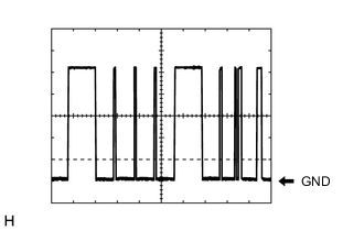
Tech Tips
The communication waveform changes according to the surrounding brightness.
| Connector Condition | Tester Connection | Condition | Specified Condition |
|---|---|---|---|
| Component without harness connected | O7-1 (SHG) - O7-2 (SHRR) | +22.09° (Vehicle Height is Low) | Approx. 1.7 V |
| 0° (Sensor Standard position) | Approx. 2.25 V | ||
| -30.18° (Vehicle Height is High) | Approx. 3.8 V |
| Connector Condition | Tester Connection | Condition | Specified Condition |
|---|---|---|---|
| - | 3 - 5 | Battery voltage not applied to terminals 1 and 2 | 10 kΩ or higher |
| Battery voltage applied to terminals 1 and 2 | Below 1 Ω |
| Connector Condition | Tester Connection | Condition | Specified Condition |
|---|---|---|---|
| - | 3 - 5 | Battery voltage not applied to terminals 1 and 2 | 10 kΩ or higher |
| Battery voltage applied to terminals 1 and 2 | Below 1 Ω |
| Connector Condition | Tester Connection | Condition | Specified Condition |
|---|---|---|---|
| - | 3 - 5 | Battery voltage not applied to terminals 1 and 2 | 10 kΩ or higher |
| Battery battery voltage applied to terminals 1 and 2 | Below 1 Ω |
| Connector Condition | Tester Connection | Condition | Specified Condition |
|---|---|---|---|
| - | 3 - 5 | Battery voltage not applied to terminals 1 and 2 | 10 kΩ or higher |
| Battery battery voltage applied to terminals 1 and 2 | Below 1 Ω |
| Connector Condition | Tester Connection | Condition | Specified Condition |
|---|---|---|---|
| - | 3 - 5 | Battery voltage not applied to terminals 1 and 2 | 10 kΩ or higher |
| Battery battery voltage applied to terminals 1 and 2 | Below 1 Ω |