БЛОК МЕХАНИЧЕСКОЙ ТРАНСМИССИИ ПОВТОРНАЯ СБОРКА

PROCEDURE
-
INSTALL STRAIGHT PIN AND RING PIN
Note
It is not necessary to remove a straight pin and ring pin unless it is being replaced.
-
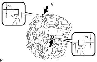
*a Protrusion Height Using a plastic-faced hammer, tap 2 new straight pins into the rear transmission case sub-assembly.
Specified Condition Item Specified Condition A 5.5 to 6.5 mm (0.2166 to 0.2559 in.) -
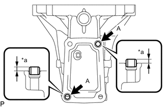
*a Protrusion Height Using a plastic-faced hammer, tap 2 new ring pins into the extension housing sub-assembly.
Specified Condition Item Specified Condition A 3.5 to 4.5 mm (0.1378 to 0.1771 in.) -
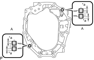
*a Protrusion Height Using a plastic-faced hammer, tap 4 new ring pins into the intermediate plate.
Specified Condition Item Specified Condition A 5.5 to 7.5 mm (0.2166 to 0.2952 in.) -
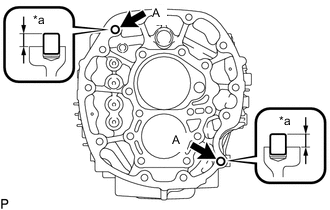
*a Protrusion Height Using a plastic-faced hammer, tap 2 new straight pins into the front transmission case sub-assembly.
Specified Condition Item Specified Condition A 9.5 to 10.5 mm (0.3741 to 0.4133 in.)
-
-
INSTALL NO. 3 GEAR SHIFT FORK SHAFT
-
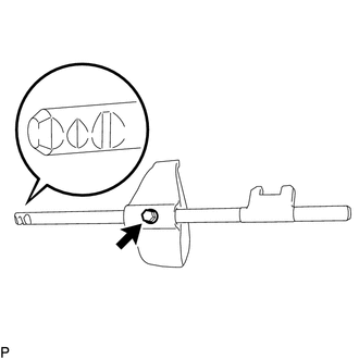
Install the No. 3 gear shift fork to the No. 3 gear shift fork shaft with a new bolt.
- Torque:
- 19.5 N*m { 199 kgf*cm, 14 ft.*lbf }
Note
Secure the shift fork with the bolt from the side as shown in the illustration.
-
-
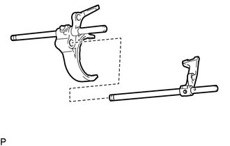
INSTALL NO. 1 GEAR SHIFT FORK SHAFT
-
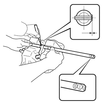
Pass the No. 1 gear shift fork shaft through the No. 1 gear shift fork head, set the shaft on the cloth that was placed on the 2 V-blocks, and then hold the shaft in place as shown in the illustration.
CAUTION:
-
Make sure to perform this procedure with 2 people and firmly hold the gear shift fork shaft in place.
-
Make sure to protect the gear shift fork shaft with a cloth before performing this procedure. If the gear shift fork shaft is damaged, shifting operations will worsen.
-
-
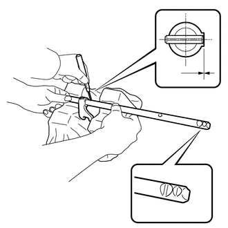
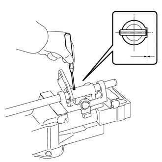
Using a 5 mm pin punch and hammer, tap a new slotted pin into the No. 1 gear shift head and No. 1 gear shift fork shaft.
Standard depth 0 to 0.5 mm (0 to 0.0196 in.) Note
Secure the gear shift head with the new slotted pin from the side as shown in the illustration.
-
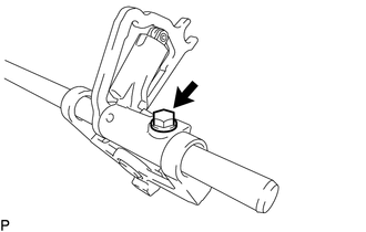
Install the No. 1 gear shift fork to the No. 1 gear shift fork shaft with a new bolt.
- Torque:
- 19.5 N*m { 199 kgf*cm, 14 ft.*lbf }
Note
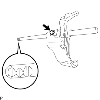
Secure the shift fork with the bolt from the side as shown in the illustration.
-
-
INSTALL NO. 4 GEAR SHIFT FORK SHAFT
-
Pass the No. 4 gear shift fork shaft through the No. 4 gear shift fork head, set the shaft on the cloth that was placed on the 2 V-blocks, and then hold the shaft in place as shown in the illustration.
CAUTION:
-
Make sure to perform this procedure with 2 people and firmly hold the gear shift fork shaft in place.
-
Make sure to protect the gear shift fork shaft with a cloth before performing this procedure. If the gear shift fork shaft is damaged, shifting operations will worsen.
-
-
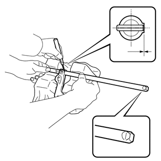
Using a 5 mm pin punch and hammer, tap a new slotted pin into the No. 4 gear shift head and No. 4 gear shift fork shaft.
Standard depth 0 to 0.5 mm (0 to 0.0196 in.) Note
Secure the gear shift head with the new slotted pin from the side as shown in the illustration.
-
Install the No. 4 gear shift fork shaft to the No. 1 gear shift fork.
-
-
INSTALL NO. 2 GEAR SHIFT FORK SHAFT
-
Pass the No. 2 gear shift fork shaft through the No. 2 gear shift fork head, set the shaft on the cloth that was placed on the 2 V-blocks, and then hold the shaft in place as shown in the illustration.
CAUTION:
-
Make sure to perform this procedure with 2 people and firmly hold the gear shift fork shaft in place.
-
Make sure to protect the gear shift fork shaft with a cloth before performing this procedure. If the gear shift fork shaft is damaged, shifting operations will worsen.
-
-
Using a 5 mm pin punch and hammer, tap a new slotted pin into the No. 2 gear shift head and No. 2 gear shift fork shaft.
Standard depth 0 to 0.5 mm (0 to 0.0196 in.) Note
Secure the gear shift head with the new slotted pin from the side as shown in the illustration.
-
Install the No. 2 gear shift fork shaft to the No. 1 gear shift fork head.
-
Install the No. 2 gear shift fork to the No. 2 gear shift fork shaft with a new bolt.
- Torque:
- 19.5 N*m { 199 kgf*cm, 14 ft.*lbf }
Note
Secure the shift fork with the bolt from the side as shown in the illustration.
-
-
INSTALL NEEDLE ROLLER BEARING
-
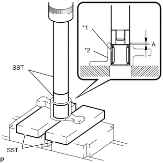
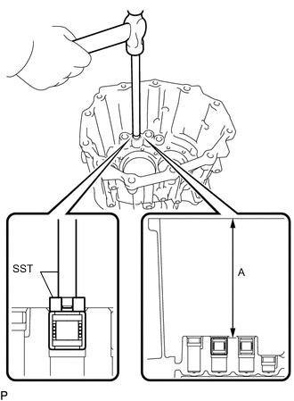
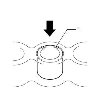
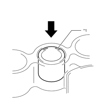
*1 Needle Roller Bearing *2 Shift Arm Using SST and a press, install a new needle roller bearing into the shift arm so that dimension A in the illustration is as specified.
- SST
- 09950-60010 ( 09951-00220 )
- 09950-70010 ( 09951-07100 )
- 09527-20011
Dimension A 0.5 to 1.5 mm (0.0197 to 0.0591 in.) Note
Press the engraved surface to install the bearing.
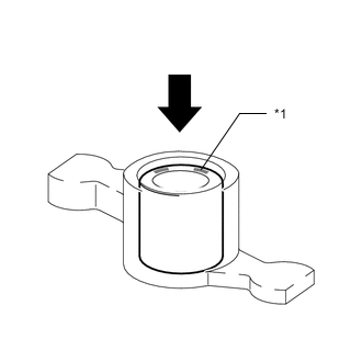
*1 Engraved Surface 
Press
-
-
INSTALL SHIFT INTERLOCK PLATE SUB-ASSEMBLY
-
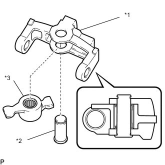
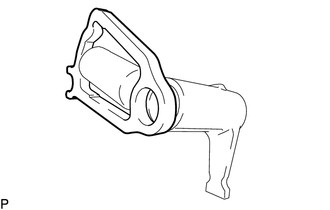
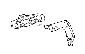
*1 Shift Interlock Plate Sub-assembly *2 Shift Arm Pivot *3 Shift Arm Coat the shift fork shaft bearing with gear oil, and then install the shift arm and shift arm pivot to the shift interlock plate sub-assembly.
-
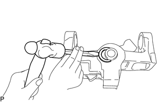
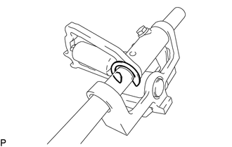
Install a new snap ring to the shift arm pivot
-
-
INSTALL SHIFT AND SELECT LEVER SHAFT
-
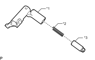
*1 Inner Select Lever *2 Select Return Compression Spring *3 No. 2 Lock Ball Pin Coat the No. 2 lock ball pin with the gear oil.
-
Install the No. 2 lock ball pin and select return compression spring to the inner select lever.
-
Install the shift and select cam to the inner select lever.
-
Align the inner select lever with the shift interlock plate sub-assembly, and then insert the inner select lever.
-
Install the shift and select shaft to the shift interlock plate and inner select lever.
-
Using a 5 mm pin punch and hammer, tap a new slotted pin into the inner select lever and shift and select lever shaft.
Standard Depth 0 to 0.5 mm (0 to 0.0196 in.) Note
Face the shaft groove towards the shift and select cam, and then tap in the pin as shown in the illustration.
-
Install a new bolt.
- Torque:
- 50.1 N*m { 511 kgf*cm, 37 ft.*lbf }
-
Install a new e-ring to the shift and select lever shaft.
-
Check that shaft operates smoothly.
-
-
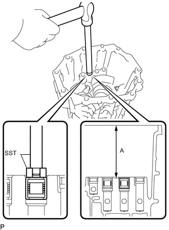
INSTALL SHIFT FORK SHAFT BEARING
-
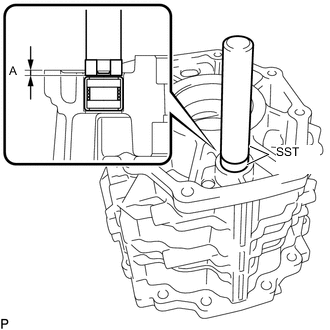
Using SST and a hammer, tap 2 new shift fork shaft bearings (front side) into the front transmission case sub-assembly so that dimension A in the illustration is as specified.
- SST
- 09950-70010 ( 09951-07360 )
- 09950-60010 ( 09951-00180 )
Dimension A 147.7 to 148.7 mm (5.815 to 5.854 in.) Note
Press the engraved surface to install the bearing.
*1 Engraved Surface Press
-
-
INSTALL SHIFT AND SELECT LEVER SHAFT NEEDLE ROLLER BEARING
-
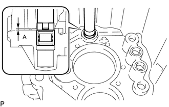
Using SST and a hammer, tap a new shift and select lever shaft needle roller bearing (front side) into the front transmission case sub-assembly so that dimension A in the illustration is as specified.
- SST
- 09950-70010 ( 09951-07360 )
- 09950-60010 ( 09951-00230 )
Dimension A 0.5 to 1.5 mm (0.0197 to 0.0590 in.) Note
Press the engraved surface to install the bearing.
*1 Engraved Surface Press
-
-
INSTALL SHIFT FORK SHAFT BEARING
-
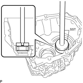
Using SST and a hammer, tap 2 new shift fork shaft bearings (rear side) into the rear transmission case sub-assembly so that dimension A in the illustration is as specified.
- SST
- 09950-70010 ( 09951-07360 )
- 09950-60010 ( 09951-00180 )
Dimension A 106.9 to 107.9 mm (4.209 to 4.248 in.) Note
Press the engraved surface to install the bearing.
*1 Engraved Surface
-
-
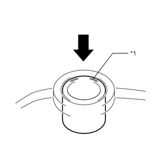
INSTALL SHIFT AND SELECT LEVER SHAFT NEEDLE ROLLER BEARING
-
Using SST and a hammer, tap a new shift and select lever shaft needle roller bearing (rear side) into the rear transmission case sub-assembly so that dimension A in the illustration is as specified.
- SST
- 09950-70010 ( 09951-07100 )
- 09950-60010 ( 09951-00230 )
Dimension A 2.5 to 3.5 mm (0.0985 to 0.1377 in.) Note
Press the engraved surface to install the bearing.
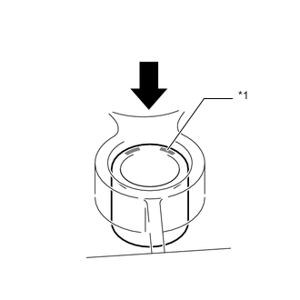
*1 Engraved Surface
-
-
INSTALL REAR COUNTER GEAR BEARING OR ROLLER
-
Coat a new rear counter gear bearing or roller (outer race) with gear oil, and then using SST and a press, install it to the rear transmission case.
- SST
- 09950-70010 ( 09951-07360 )
- 09950-60010 ( 09951-00710 )
-
Install the bolt and bearing lock plate.
- Torque:
- 11.3 N*m { 115 kgf*cm, 8 ft.*lbf }
-
-
INSTALL FRONT OUTPUT SHAFT BEARING
-
Using SST and a press, install a new front output shaft bearing (outer race) to the rear transmission case sub-assembly.
- SST
- 09950-70010 ( 09951-07360 )
- 09951-00850
-
-
INSTALL REAR OUTPUT SHAFT BEARING
-
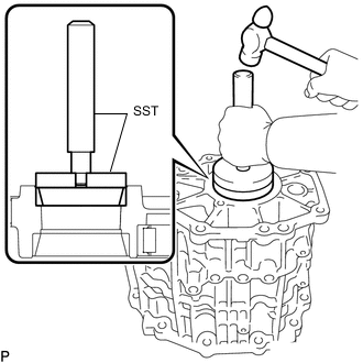
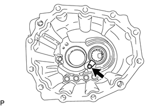
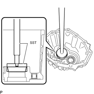
Using SST and a hammer, install a new rear output shaft bearing (outer race) to the rear transmission case sub-assembly.
- SST
- 09950-70010 ( 09951-07100 )
- 09950-60020 ( 09951-00790 )
-
-
INSTALL FRONT OUTPUT SHAFT BEARING
-
INSPECT PRELOAD
-
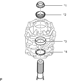
*1 Manual Transmission Output Shaft Rear Set Nut *2 Rear Output Shaft Bearing *3 Output Shaft Spacer *4 Rear Output Shaft Bearing Shim Temporarily install the output shaft, rear output shaft bearing shim, output shaft spacer, rear output shaft bearing and a new manual transmission output shaft rear set nut to the rear transmission case sub-assembly.
Note
-
Do not apply gear oil to a new output shaft bearing and rear output shaft bearing. If applied, the turning torque cannot be accurately measured.
-
If the turning torque is not properly measured, the output shaft bearing may generate abnormal noise and become damaged.
-
-
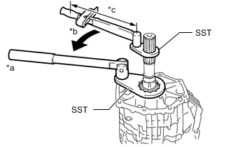
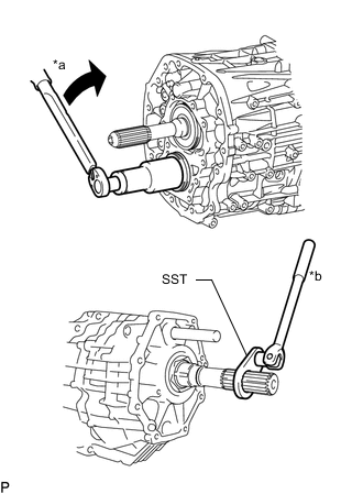
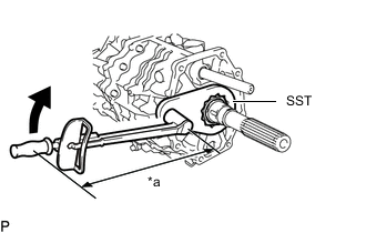
*a Hold *b Turn *c Fulcrum Length Temporarily install the manual transmission output shaft rear set nut to the output shaft.
- SST
- 09326-35020
- 09326-71010
- Torque:
- 50 N*m { 510 kgf*cm, 37 ft.*lbf }
Note
If the nut is not temporarily installed, the position of the rear output shaft bearing will be unstable causing the preload to be unstable.
-
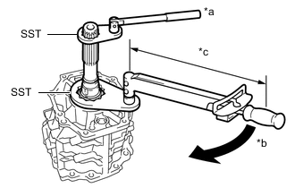
*a Hold *b Turn *c Fulcrum Length Using SST and a torque wrench, tighten the manual transmission output shaft rear set nut.
- SST
- 09326-35020
- 09326-71010
- Torque:
- Specified tightening torque
- 187 N*m { 1907 kgf*cm, 138 ft.*lbf }
Tech Tips
-
Calculate the torque wrench reading when changing the fulcrum length of the torque wrench.
-
When using SST (fulcrum length of 50 mm (1.9685 in.)) + torque wrench (fulcrum length of 1055 mm (41.5354 in.)): 178.5 N*m (1820 kgf*cm, 132 ft.*lbf)
-
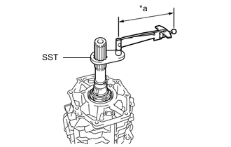
*a Fulcrum Length Using SST and a torque wrench, measure the turning torque of the output shaft bearing while rotating SST at 60 rpm.
Standard turning torque at 60 rpm New output shaft bearing 0.21 to 1.32 N*m (2.14 to 13.46 kgf*cm, 1.86 to 11.68 in.*lbf) Note
-
Do not apply gear oil to a new output shaft bearing and rear output shaft bearing. If applied, the turning torque cannot be accurately measured.
-
If the turning torque is not properly measured, the output shaft bearing may generate abnormal noise and become damaged.
Tech Tips
-
Calculate the torque wrench reading when changing the fulcrum length of the torque wrench.
-
New output shaft bearing:
When using SST (fulcrum length of 50 mm (1.969 in.)) + torque wrench (fulcrum length of 160 mm (6.299 in.)): 0.16 to 1.00 N*m (1.64 to 10.19 kgf*cm, 1.42 to 8.85 in.*lbf)
If the torque is more than the standard, replace the output shaft shim.
Tech Tips
New output shaft bearing:
When the thickness of the shim is increased by 0.016 mm (0.0006 in.), the preload is reduced by 0.45 N*m (4.59 kgf*cm, 3.98 in.*lbf).
Standard Shim Thickness Part No. Mark Thickness Part No. Mark Thickness 90564-T0020 01 2.214 to 2.230 mm (0.0872 to 0.0877 in.) 90564-T0044 25 2.598 to 2.614 mm (0.1023 to 0.1029 in.) 90564-T0021 02 2.230 to 2.246 mm (0.0878 to 0.0884 in.) 90564-T0045 26 2.614 to 2.630 mm (0.1030 to 0.1035 in.) 90564-T0022 03 2.246 to 2.262 mm (0.0885 to 0.0890 in.) 90564-T0046 27 2.630 to 2.646 mm (0.1036 to 0.1041 in.) 90564-T0023 04 2.262 to 2.278 mm (0.0891 to 0.0896 in.) 90564-T0047 28 2.646 to 2.662 mm (0.1042 to 0.1048 in.) 90564-T0024 05 2.278 to 2.294 mm (0.0897 to 0.0903 in.) 90564-T0048 29 2.662 to 2.678 mm (0.1049 to 0.1054 in.) 90564-T0025 06 2.294 to 2.310 mm (0.0904 to 0.0909 in.) 90564-T0049 30 2.678 to 2.694 mm (0.1055 to 0.1060 in.) 90564-T0026 07 2.310 to 2.326 mm (0.0910 to 0.0915 in.) 90564-T0050 31 2.694 to 2.710 mm (0.1061 to 0.1066 in.) 90564-T0027 08 2.326 to 2.342 mm (0.0916 to 0.0922 in.) 90564-T0051 32 2.710 to 2.726 mm (0.1067 to 0.1073 in.) 90564-T0028 09 2.342 to 2.358 mm (0.0923 to 0.0928 in.) 90564-T0052 33 2.726 to 2.742 mm (0.1074 to 0.1079 in.) 90564-T0029 10 2.358 to 2.374 mm (0.0929 to 0.0934 in.) 90564-T0053 34 2.742 to 2.758 mm (0.1080 to 0.1085 in.) 90564-T0030 11 2.374 to 2.390 mm (0.0935 to 0.0940 in.) 90564-T0054 35 2.758 to 2.774 mm (0.1086 to 0.1092 in.) 90564-T0031 12 2.390 to 2.406 mm (0.0941 to 0.0947 in.) 90564-T0055 36 2.774 to 2.790 mm (0.1093 to 0.1098 in.) 90564-T0032 13 2.406 to 2.422 mm (0.0948 to 0.0953 in.) 90564-T0056 37 2.790 to 2.806 mm (0.1099 to 0.1104 in.) 90564-T0033 14 2.422 to 2.438 mm (0.0954 to 0.0959 in.) 90564-T0057 38 2.806 to 2.822 mm (0.1105 to 0.1111 in.) 90564-T0034 15 2.438 to 2.454 mm (0.0960 to 0.0966 in.) 90564-T0058 39 2.822 to 2.838 mm (0.1112 to 0.1117 in.) 90564-T0035 16 2.454 to 2.470 mm (0.0967 to 0.0972 in.) 90564-T0059 40 2.838 to 2.854 mm (0.1118 to 0.1123 in.) 90564-T0036 17 2.470 to 2.486 mm (0.0973 to 0.0978 in.) 90564-T0060 41 2.854 to 2.870 mm (0.1124 to 0.1129 in.) 90564-T0037 18 2.486 to 2.502 mm (0.0979 to 0.0985 in.) 90564-T0061 42 2.870 to 2.886 mm (0.1130 to 0.1136 in.) 90564-T0038 19 2.502 to 2.518 mm (0.0986 to 0.0991 in.) 90564-T0062 43 2.886 to 2.902 mm (0.1137 to 0.1142 in.) 90564-T0039 20 2.518 to 2.534 mm (0.0992 to 0.0997 in.) 90564-T0063 44 2.902 to 2.918 mm (0.1143 to 0.1148 in.) 90564-T0040 21 2.534 to 2.550 mm (0.0998 to 0.1003 in.) 90564-T0064 45 2.918 to 2.934 mm (0.1149 to 0.1155 in.) 90564-T0041 22 2.550 to 2.566 mm (0.1004 to 0.1010 in.) 90564-T0065 46 2.934 to 2.950 mm (0.1156 to 0.1161 in.) 90564-T0042 23 2.566 to 2.582 mm (0.1011 to 0.1016 in.) 90564-T0066 47 2.950 to 2.966 mm (0.1162 to 0.1167 in.) 90564-T0043 24 2.582 to 2.598 mm (0.1017 to 0.1022 in.) - - - -
-
-
INSTALL COUNTER GEAR
-
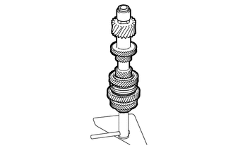
Install the counter gear to SST.
- SST
- 09310-71010
-
-
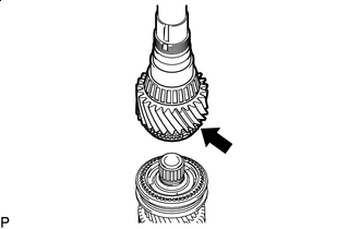
INSTALL INPUT SHAFT
-
Install the input shaft to SST.
- SST
- 09310-71010
-
-
INSTALL NO. 4 SYNCHRONIZER RING
-
Coat the No. 4 synchronizer ring with the gear oil.
-
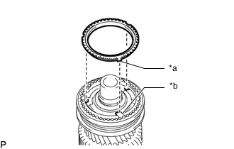
*a Protrusion *b Groove Install the No. 4 synchronizer ring to the transmission unit.
Tech Tips
Align the protrusion of the No. 4 synchronizer ring with the groove of the No. 2 transmission clutch hub
-
-
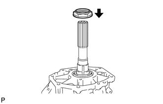
INSTALL INPUT SHAFT BEARING
-
Coat the input shaft bearing with the gear oil.
-
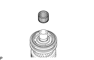
Install the input shaft bearing to the transmission unit.
-
-
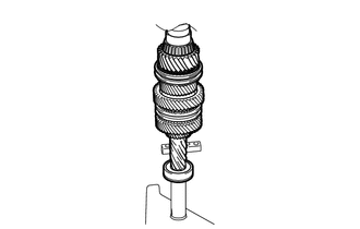
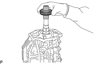
INSTALL OUTPUT SHAFT
-
Gear Oil Coat the output shaft with the gear oil as shown in the illustration.
-
Install the output shaft to the transmission unit.
-
Contract SST and connect the input shaft to the counter gear.
-
-
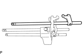
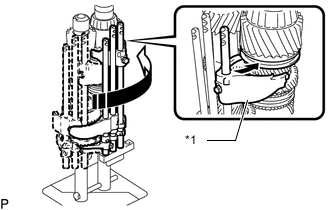
INSTALL SHIFT FORK AND SHIFT FORK SHAFT ASSEMBLY
-

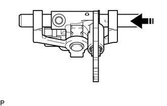
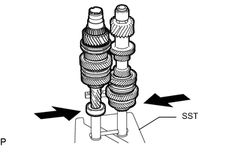
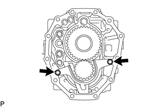
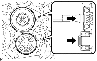
Install in this direction Move the 2 sleeves shown in the illustration in the direction indicated by the arrows
-
Temporarily install the No. 4 gear shift fork to the No. 4 gear shift fork shaft.
-
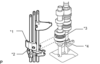
*1 No. 1 Gear Shift Fork *2 No. 4 Gear Shift Fork *3 No. 1 Transmission Hub Sleeve *4 No. 4 Transmission Hub Sleeve Set the No. 1 gear shift fork onto the No. 1 transmission hub sleeve, and the No. 4 gear shift fork onto the No. 4 transmission hub sleeve.
Note
Do not drop the No. 4 gear shift fork.
-
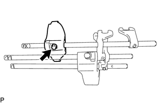
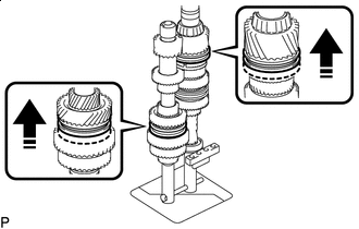
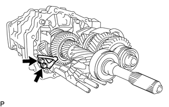
*1 No. 2 Gear Shift Fork Install in this direction Move the part as shown in the illustration and set the No. 2 gear shift fork onto the No. 2 transmission hub sleeve.
-
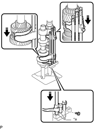
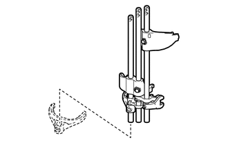
*a Depressions of SST Install in this direction Install the shift fork shaft to the depression of SST.
-
Install the No. 4 gear shift fork to the No. 4 gear shift fork shaft with a new bolt.
- Torque:
- 19.5 N*m { 199 kgf*cm, 14 ft.*lbf }
Note
-
Securely install the No. 4 gear shift fork with a new bolt from the side of the shaft as shown in the illustration.
-
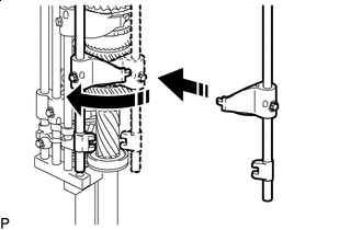
Install in this direction Install the No. 3 gear shift fork to the No. 3 transmission hub sleeve, and then move it as shown in the illustration.
-
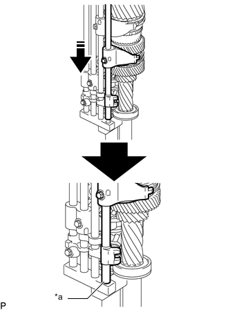
*a Depression of SST Install in this direction Install the shift fork shaft to the depression of SST.
-
-
INSTALL REVERSE IDLER GEAR
-
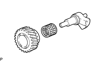
Coat the reverse idler gear with the gear oil.
-
Install the reverse idler gear and reverse idler gear bearing to the reverse idler gear shaft.
-
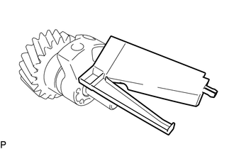
Install the No. 2 oil receiver pipe to the reverse idler gear shaft.
-
-
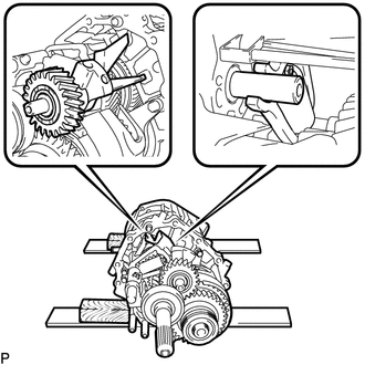
INSTALL MANUAL TRANSMISSION CASE SUB-ASSEMBLY
-
Install the manual transmission oil separator sub-assembly (rear side) to the transmission unit.
-
Install the No. 3 oil receiver pipe to the rear transmission case sub-assembly.
-
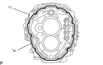
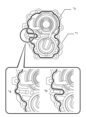
*1 Transmission Inter Plate Sub-assembly *a Seal Packing Apply seal packing to the transmission intermediate plate shown in the illustration.
Seal Packing Toyota Genuine Seal Packing 1281, Three Bond 1281 or equivalent Note
Parts must be assembled within 10 minutes of application. Otherwise, the seal packing (FIPG material) must be removed and reapplied.
-
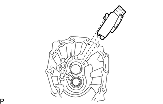
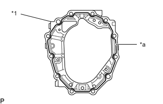
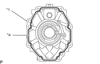
*1 Manual Transmission Case Sub-assembly *a Seal Packing Apply seal packing to the manual transmission case sub-assembly shown in the illustration.
Seal Packing Toyota Genuine Seal Packing 1281, Three Bond 1281 or equivalent Note
Parts must be assembled within 10 minutes of application. Otherwise, the seal packing (FIPG material) must be removed and reapplied.
-
*a Tape Application Prohibited Install the rear transmission case sub-assembly and intermediate plate.
Note
-
Secure the rear transmission case sub-assembly and intermediate plate with tape.
-
Make sure that the tape does not contact the seal packing application surface of the manual transmission case sub-assembly.
-
-
Install the rear transmission case sub-assembly.
-
Install the rear output shaft bearing to the transmission unit.
-
Temporarily install the manual transmission output shaft rear set nut to the transmission unit.
-
*a Hold *b Turn *c Fulcrum length Temporarily install the manual transmission output shaft rear set nut.
- SST
- 09326-35020
- Torque:
- 50 N*m { 510 kgf*cm, 37 ft.*lbf }
CAUTION:
Since the manual transmission unit is very heavy, perform these procedures with 2 people.
Note
If the nut is not temporarily installed, the position of the rear output shaft will be unstable causing the preload to be unstable.
-
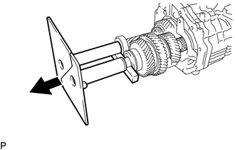
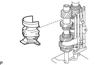
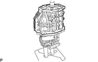
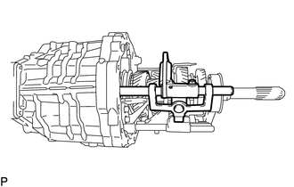
Lay the transmission unit on its side, and then remove SST from the transmission unit as shown in the illustration.
- SST
- 09310-71010
CAUTION:
Since the manual transmission unit is very heavy, perform these procedures with 2 people.
Note
Lay the transmission unit on its side so that the shift fork shaft sub-assembly is on the bottom.
-
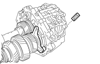
Install the transmission magnet.
-
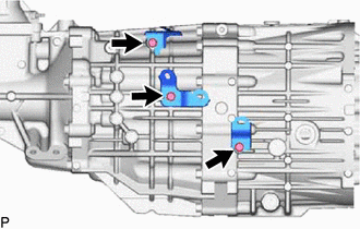
Install the transmission oil separator sub-assembly (front side) to the transmission unit with the 2 bolts.
- Torque:
- 18 N*m { 184 kgf*cm, 13 ft.*lbf }
CAUTION:
Since the manual transmission unit is very heavy, perform these procedures with 2 people.
-
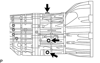
Install the shift interlock plate stopper to the transmission unit with the 2 bolts.
- Torque:
- 23.8 N*m { 243 kgf*cm, 18 ft.*lbf }
CAUTION:
Since the manual transmission unit is very heavy, perform these procedures with 2 people.
-
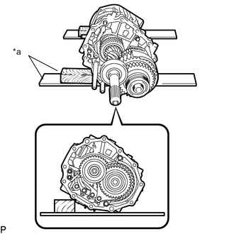
*a Wooden Block Use wooden blocks or other objects to support the corners of the transmission unit as shown in the illustration before conducting work.
-
Install the shift and select lever shaft sub-assembly to the transmission unit.
CAUTION:
Since the manual transmission unit is very heavy, perform these procedures with 2 people.
-
Align the groove of the shift and select cam with the reverse idler shaft, and then install the reverse idler gear.
CAUTION:
Since the manual transmission unit is very heavy, perform these procedures with 2 people.
-
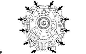
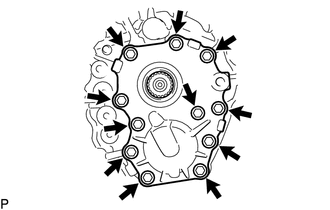
Install the manual transmission case sub-assembly with the 12 bolts.
- Torque:
- 37 N*m { 377 kgf*cm, 27 ft.*lbf }
CAUTION:
Since the manual transmission unit is very heavy, perform these procedures with 2 people.
-
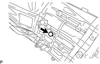
Install the reverse idler gear shaft bolt and a new gasket to the reverse idler gear shaft.
- Torque:
- 25 N*m { 255 kgf*cm, 18 ft.*lbf }
CAUTION:
Since the manual transmission unit is very heavy, perform these procedures with 2 people.
-
-
INSTALL INPUT SHAFT SHAFT SNAP RING
-
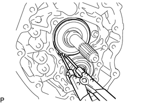
Using snap ring pliers, install a new input shaft shaft snap ring.
-
-
INSTALL FRONT BEARING SHAFT SNAP RING
-
Using a snap ring expander, install a new front bearing shaft snap ring.
-
-
INSTALL COUNTER GEAR SHAFT NUT
-
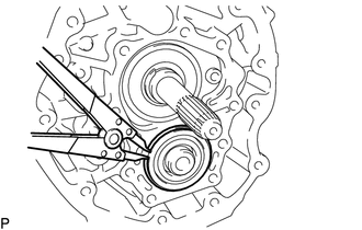
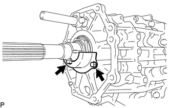
*a Turn *b Hold Using SST, secure the output shaft.
- SST
- 09326-35020
-
Using a 41 mm socket wrench, install a new counter gear shaft nut.
- Torque:
- 40 N*m { 408 kgf*cm, 30 ft.*lbf }
CAUTION:
Since the manual transmission unit is very heavy, perform these procedures with 2 people.
-
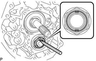
Using a chisel and hammer, stake the counter gear shaft nut.
-
Push Push in the input shaft and counter gear so that the 2 snap rings are firmly pressed into the transmission case.
-
-
INSTALL FRONT TRANSMISSION BEARING RETAINER OIL SEAL
-
INSTALL FRONT BEARING RETAINER
-
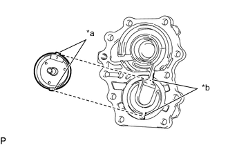
*1 Front Bearing Retainer *a Incorrect *b Correct *c Seal Packing Apply seal packing to the front bearing retainer shown in the illustration.
Seal Packing Toyota Genuine Seal Packing 1281, Three Bond 1281 or equivalent Note
Parts must be assembled within 10 minutes of application. Otherwise, the seal packing (FIPG material) must be removed and reapplied.
-
*a Protrusion *b Groove Install the No. 1 oil receiver pipe to the front bearing retainer.
Tech Tips
Align the protrusion of the No. 1 oil receiver pipe with the groove of the front bearing retainer.
-
Install the front bearing retainer to the front transmission case with new 11 bolts.
- Torque:
- 40 N*m { 408 kgf*cm, 30 ft.*lbf }
CAUTION:
Since the manual transmission unit is very heavy, perform these procedures with 2 people.
-
-
INSTALL CLUTCH HOUSING
-
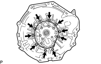
Install the clutch housing to the manual transmission case sub-assembly with the 10 bolts.
- Torque:
- 36 N*m { 367 kgf*cm, 27 ft.*lbf }
CAUTION:
Since the manual transmission unit is very heavy, perform these procedures with 2 people.
-
-
TIGHTEN MANUAL TRANSMISSION OUTPUT SHAFT REAR SET NUT
CAUTION:
Since the manual transmission unit is very heavy, perform these procedures with 2 people.
-
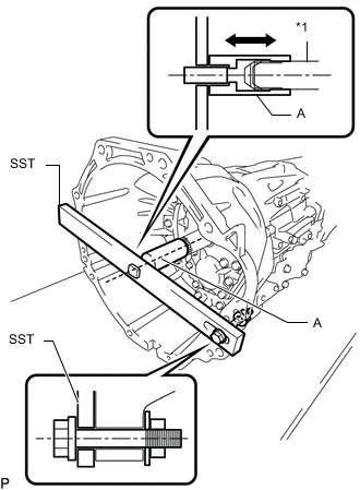
*1 Input Shaft Engage the gear, and then secure the input shaft using SST.
- SST
- 09322-35010 ( 09322-03010, 09322-03020, 09322-03030, 90105-12087, 90170-12030, 94622-51200 )
Tech Tips
-
Install SST securely so that the part labeled A is in-line with the input shaft.
-
Make sure that the part labeled A moves back and forth by hand after installing SST.
-
*a Fulcrum Length Using an L-type handle and SST, install the manual transmission output shaft rear set nut to the output shaft sub-assembly.
- SST
- 09326-35020
- Torque:
- 187 N*m { 1907 kgf*cm, 138 ft.*lbf }
Tech Tips
-
Calculate the torque wrench reading when changing the fulcrum length of the torque wrench.
-
When using SST (fulcrum length of 50 mm (1.9685 in.)) + torque wrench (fulcrum length of 1055 mm (41.5354 in.)): 178.5 N*m (1820 kgf*cm, 132 ft.*lbf)
-
-
STAKE MANUAL TRANSMISSION OUTPUT SHAFT REAR SET NUT
-
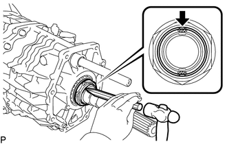
Using a chisel and hammer, stake the manual transmission output shaft rear set nut.
-
-
INSTALL TRANSMISSION OIL RUNNER
-
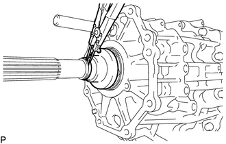
Install the transmission oil runner to the output shaft sub-assembly.
-
Using a snap ring expander, install a new snap ring to the output shaft sub-assembly.
-
-
INSTALL TRANSMISSION OIL SEPARATOR
-
Install the 2 bolts and transmission oil separator.
- Torque:
- 11.3 N*m { 115 kgf*cm, 8 ft.*lbf }
-
-
INSTALL MANUAL TRANSMISSION EXTENSION HOUSING OIL SEAL
-
INSTALL NO. 4 OIL RECEIVER PIPE
-
Install the No. 4 oil receiver pipe to the extension housing sub-assembly.
-
-
INSTALL EXTENSION HOUSING SUB-ASSEMBLY
CAUTION:
Since the manual transmission unit is very heavy, perform these procedures with 2 people.
-
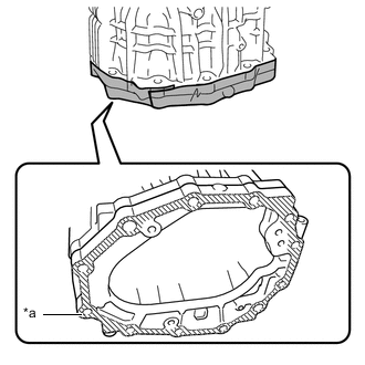
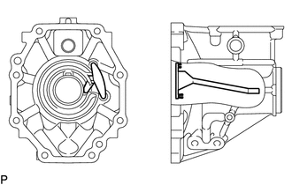
*1 Extension Housing Sub-assembly *a Seal Packing Apply seal packing to the extension housing sub-assembly shown in the illustration.
Seal Packing Toyota Genuine Seal Packing 1281, Three Bond 1281 or equivalent Note
Parts must be assembled within 10 minutes of application. Otherwise, the seal packing (FIPG material) must be removed and reapplied.
-
Install the extension housing sub-assembly to the rear transmission case with the 8 bolts.
- Torque:
- 29 N*m { 296 kgf*cm, 21 ft.*lbf }
-
-
INSTALL SHIFT LEVER HOUSING
-
Install a new bolt and shift lever housing.
- Torque:
- 50.1 N*m { 511 kgf*cm, 37 ft.*lbf }
Note
Do not damage the sealing surface of the control shift lever retainer sub-assembly
-
-
INSTALL FLOOR SHIFT CONTROL SHIFT LEVER RETAINER SUB-ASSEMBLY
-
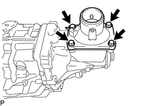
Install the floor shift control shift lever retainer sub-assembly and new control shift lever retainer gasket to the extension housing sub-assembly with the 4 bolts.
- Torque:
- 18 N*m { 184 kgf*cm, 13 ft.*lbf }
-
-
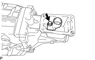
INSTALL LOCK BALL PIN
-
Install the lock ball pin and shift and select lever spring to the rear transmission case.
-
Using a 10 mm hexagon wrench, install a new No. 2 with head straight screw plug to the rear transmission case.
- Torque:
- 24.5 N*m { 250 kgf*cm, 18 ft.*lbf }
-
-
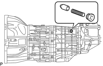
INSTALL SHAFT DETENT BALL
-
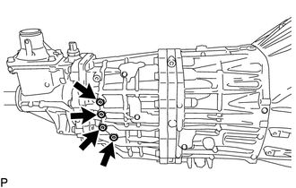
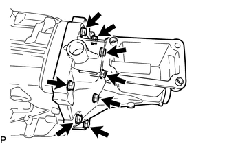
Install the 4 shaft detent balls and 4 shift detent ball compression springs to the rear transmission case.
-
Using a 6 mm hexagon wrench, install 4 new shift detent ball plugs to the rear transmission case.
- Torque:
- 22 N*m { 224 kgf*cm, 16 ft.*lbf }
-
-
INSTALL MANUAL TRANSMISSION CASE PLUG
-
Install a new gasket and the manual transmission filler plug (with label).
- Torque:
- 37 N*m { 377 kgf*cm, 27 ft.*lbf }
-
Install a new gasket and the drain plug sub-assembly (without label).
- Torque:
- 37 N*m { 377 kgf*cm, 27 ft.*lbf }
-
Using a 10 hexagon wrench, install a new gasket and the straight screw plug with head.
- Torque:
- 37 N*m { 377 kgf*cm, 27 ft.*lbf }
-
-
INSTALL TRANSMISSION REVOLUTION SENSOR (w/ Intelligent Manual Transmission Switch)
-
INSTALL BACK-UP LIGHT SWITCH BRACKET
-
Install the 3 back-up light switch brackets with the 3 bolts.
- Torque:
- 12.6 N*m { 128 kgf*cm, 9 ft.*lbf }
-
-
INSTALL BACK-UP LIGHT SWITCH ASSEMBLY
-
INSTALL RELEASE FORK SUPPORT
-
INSTALL CLUTCH RELEASE BEARING ASSEMBLY