БЛОК МЕХАНИЧЕСКОЙ ТРАНСМИССИИ РАЗБОРКА

PROCEDURE
-
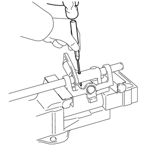
REMOVE CLUTCH RELEASE BEARING ASSEMBLY
-
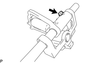
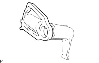
REMOVE RELEASE FORK SUPPORT
-
REMOVE BACK-UP LIGHT SWITCH ASSEMBLY
-
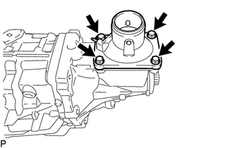
REMOVE BACK-UP LIGHT SWITCH BRACKET
-
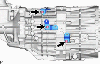
Remove the 3 bolts and back-up light switch brackets.
-
-
REMOVE TRANSMISSION REVOLUTION SENSOR (w/ Intelligent Manual Transmission Switch)
-
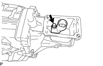
REMOVE MANUAL TRANSMISSION CASE PLUG
-
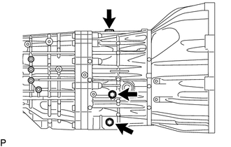
Remove the manual transmission filler plugs, drain plug sub-assembly and 2 gaskets from the manual transmission case sub-assembly.
-
Using a 10 mm hexagon wrench, remove the straight screw plug with head from the rear transmission case.
-
-
REMOVE SHAFT DETENT BALL
-
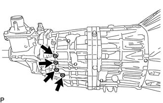
Using a 6 mm hexagon wrench, remove the 4 shift detent ball plugs from the rear transmission case.
-
Remove the 4 shift detent ball compression springs and 4 shift detent balls from the rear transmission case.
-
-
REMOVE LOCK BALL PIN
-
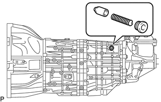
Using a 10 mm hexagon wrench, remove the No. 2 with head straight screw plug from the rear transmission case.
-
Remove the lock ball pin and shift and select lever spring from the rear transmission case.
-
-
REMOVE FLOOR SHIFT CONTROL SHIFT LEVER RETAINER SUB-ASSEMBLY
-
Remove the 4 bolts and then remove the floor shift control shift lever retainer sub-assembly and control shift lever retainer gasket from the extension housing sub-assembly.
-
-
REMOVE SHIFT LEVER HOUSING
-
Remove the bolt and shift lever housing.
Note
Do not damage the sealing surface of the control shift lever retainer sub-assembly
-
-
REMOVE EXTENSION HOUSING SUB-ASSEMBLY
-
Remove the 8 bolts and extension housing sub-assembly.
-
-
REMOVE NO. 4 OIL RECEIVER PIPE
-
Remove the No. 4 oil receiver pipe from the extension housing sub-assembly.
-
-
REMOVE MANUAL TRANSMISSION EXTENSION HOUSING OIL SEAL
-
REMOVE TRANSMISSION OIL SEPARATOR
-
Remove the 2 bolts and transmission oil separator from the rear transmission case.
-
-
REMOVE TRANSMISSION OIL RUNNER
-
Using a snap ring expander, remove the snap ring from the output shaft sub-assembly.
-
Remove the transmission oil runner from the output shaft sub-assembly.
-
-
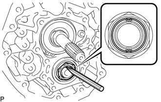
UNSTAKE MANUAL TRANSMISSION OUTPUT SHAFT REAR SET NUT
-
Using a chisel and hammer, unstake the manual transmission output shaft rear set nut.
-
-
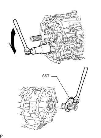
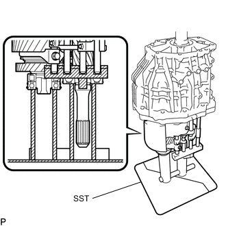
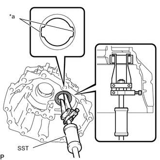
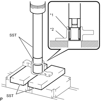
REMOVE MANUAL TRANSMISSION OUTPUT SHAFT REAR SET NUT
-
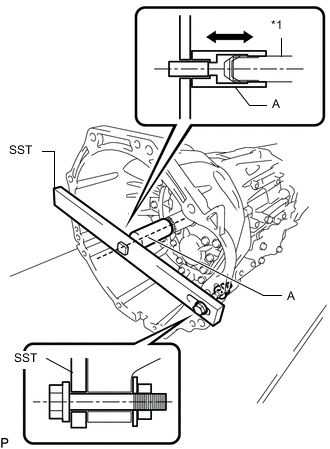
*1 Input Shaft Engage the gear, and then secure the input shaft using SST.
- SST
- 09322-35010 ( 09322-03010, 09322-03020, 09322-03030, 90105-12087, 90170-12030, 94622-51200 )
Tech Tips
-
Install SST securely so that the part labeled A is in-line with the input shaft.
-
Make sure that the part labeled A moves back and forth by hand after installing SST.
-
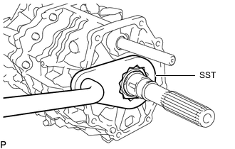
Using SST, remove the manual transmission output shaft rear set nut from the output shaft.
- SST
- 09326-35020
-
-
REMOVE CLUTCH HOUSING
-
Remove the 10 bolts.
-
Using a plastic-faced hammer, carefully tap off the clutch housing to remove it.
-
-
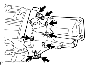
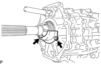
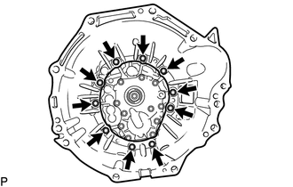
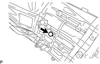
REMOVE FRONT BEARING RETAINER
-
Remove the 11 bolts.
-
Using a screwdriver wrapped in protective tape, remove the front bearing retainer by prying the points in the illustration.
Note
-
Do not damage the sealing surface of the clutch housing and manual transmission case sub-assembly.
-
Do not damage the sealing surface of the front bearing retainer and manual transmission case sub-assembly.
-
-
-
REMOVE NO. 1 OIL RECEIVER PIPE
-
Remove the No. 1 oil receiver pipe from the front bearing retainer.
-
-
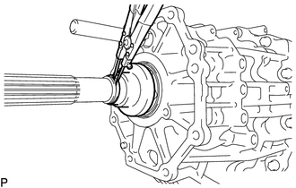
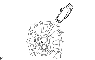
REMOVE FRONT TRANSMISSION BEARING RETAINER OIL SEAL
-
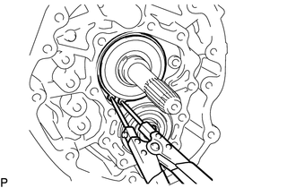
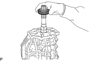
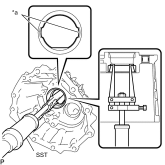
REMOVE COUNTER GEAR SHAFT NUT
-
Using a chisel and hammer, unstake the counter gear shaft nut.
-
Using SST, hold the output shaft.
- SST
- 09326-35020
-
Using a 41 mm socket wrench, remove the counter gear shaft nut.
-
-
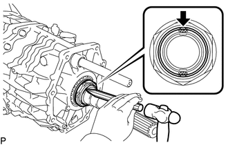
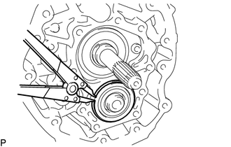
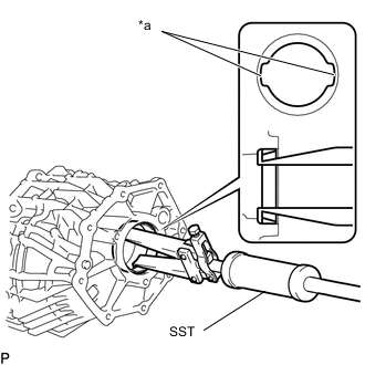
REMOVE INPUT SHAFT SHAFT SNAP RING
-
Using snap ring pliers, remove the input shaft shaft snap ring.
-
-
REMOVE FRONT BEARING SHAFT SNAP RING
-
Using a snap ring expander, remove the front bearing shaft snap ring.
-
-
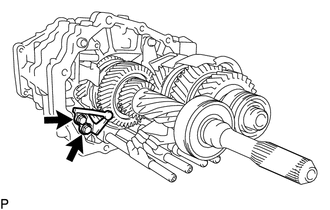
REMOVE REVERSE IDLER GEAR SHAFT BOLT
-
Remove the reverse idler gear shaft bolt and gasket from the reverse idler gear shaft.
-
-
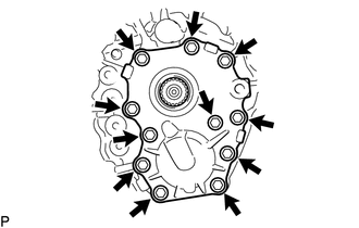
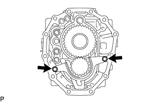
REMOVE MANUAL TRANSMISSION CASE SUB-ASSEMBLY
CAUTION:
Since the manual transmission unit is very heavy, 2 people are needed to remove the manual transmission case sub-assembly.
-
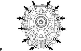
Remove the 12 bolts.
-
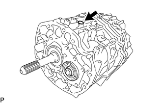
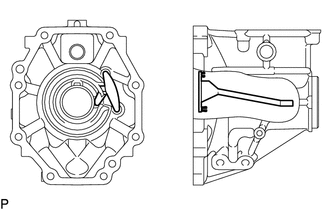
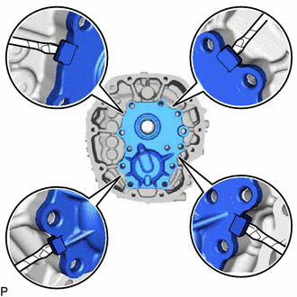
In order to prevent the reverse idler gear from falling when removing the transmission case, set the manual transmission assembly on its side so that the installation hole of the reverse idler gear stopper bolt is facing upward as shown in the illustration.
-
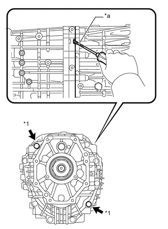
*1 Straight Pin *a Protective Tape .Using a screwdriver wrapped in protective tape, separate the transmission case sub-assembly and intermediate plate by prying at the points shown in the illustration.
Note
Do not damage the sealing surfaces of the manual transmission case sub-assembly and transmission intermediate plate.
-
Place wooden blocks or other objects underneath the rear transmission case to securely support it as shown in the illustration
-
Remove the manual transmission case sub-assembly from the rear transmission case.
-
-
REMOVE REVERSE IDLER GEAR
CAUTION:
Since the manual transmission is very heavy, perform these procedures with 2 people. While one person is removing the reverse idler gear, have the other person hold the transmission in place.
-
Remove the reverse idler gear and front oil receiver from the transmission unit.
-
Remove the No. 2 oil receiver from the reverse idler gear shaft.
-
Remove the reverse idler gear bearing and reverse idler gear from the reverse idler gear shaft.
-
-
REMOVE SHIFT AND SELECT LEVER SHAFT SUB-ASSEMBLY
-
Remove the shift and select lever shaft sub-assembly from the transmission unit.
CAUTION:
Since the manual transmission is very heavy, perform these procedures with 2 people. While one person is removing the shift and select shaft, have the other person hold the transmission in place.
-
-
REMOVE SHIFT INTERLOCK PLATE STOPPER
-
Remove the 2 bolts and shift interlock plate stopper from the transmission unit.
CAUTION:
Since the manual transmission is very heavy, perform these procedures with 2 people. While one person is removing the shift interlock plate stopper, have the other person hold the transmission in place.
-
-
REMOVE MANUAL TRANSMISSION OIL SEPARATOR SUB-ASSEMBLY
-
Remove the 2 bolts and transmission oil separator sub-assembly (front side).
CAUTION:
Since the manual transmission is very heavy, perform these procedures with 2 people. While one person is removing the manual transmission oil separator sub-assembly, have the other person hold the transmission in place.
-
-
REMOVE TRANSMISSION MAGNET
-
Remove the transmission magnet from the transmission intermediate plate.
CAUTION:
Since the manual transmission is very heavy, perform these procedures with 2 people. While one person is removing the manual transmission magnet, have the other person hold the transmission in place.
-
-
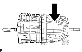
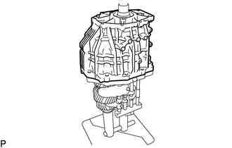
REMOVE REAR TRANSMISSION CASE
-
Using SST, set the transmission unit.
- SST
- 09310-71010
CAUTION:
Since the manual transmission unit is very heavy, 2 people are needed to set the transmission unit.
-
Stand the manual transmission upright as shown in the illustration.
CAUTION:
Since the manual transmission unit is very heavy, 2 people are needed to stand the manual transmission upright as shown in the illustration.
-
Remove the rear output shaft bearing.
-
Remove the rear transmission case and intermediate plate.
-
Remove the intermediate plate from the rear transmission case.
-
Remove the transmission oil separator sub-assembly (Rear side).
-
-
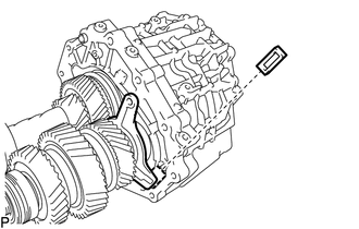
REMOVE NO. 3 OIL RECEIVER PIPE
-
Remove the No. 3 oil receiver pipe from the rear transmission case.
-
-
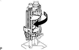
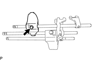
REMOVE SHIFT FORK AND SHIFT FORK SHAFT ASSEMBLY
-
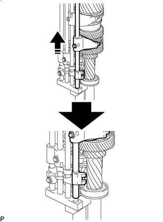

Remove in this direction Move the No. 2 hub sleeve as shown in the illustration and remove the No. 3 gear shift fork from SST as shown in the illustration.
-
Remove in this direction Slide the No. 3 gear shift fork from position 1 to 2 and then remove the No. 3 gear shift fork together with the No. 3 gear shift fork shaft.
-
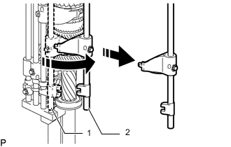
*1 No. 2 Transmission Hub Sleeve *2 No. 1 Transmission Hub Sleeve *3 No. 4 Transmission Hub Sleeve Remove in this direction Slide the No. 2 and No. 1 hub sleeves as shown in the illustration.
-
Remove the bolt from the No. 4 gear shift fork, and then slide the No. 4 gear shift fork shaft as shown in the illustration.
-
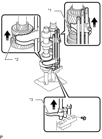
Remove in this direction Move the shift fork and shift fork shaft assembly as shown in the illustration.
Note
Move the 3 shift fork shafts together.
-
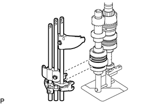
Remove the shift fork and shift fork shaft sub-assembly from the counter gear.
Note
Do not drop the No. 4 gear shift fork.
-
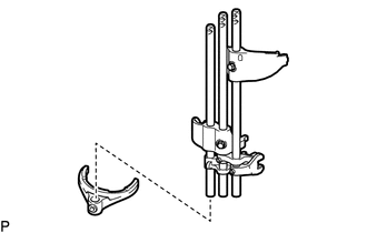
Remove the No. 4 gear shift fork.
-
-
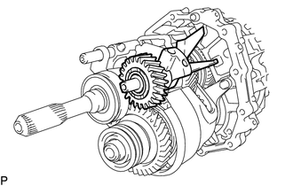
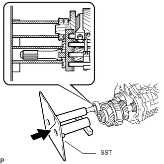
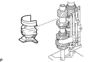
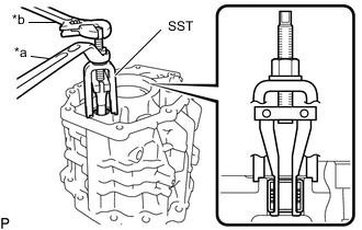
REMOVE OUTPUT SHAFT
-
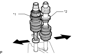
*1 Input Shaft *2 Counter Gear Expand SST to the left and right.
-
Remove the output shaft from the transmission unit.
-
Remove the output shaft spacer and rear output shaft bearing shim.
-
-
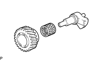
REMOVE INPUT SHAFT BEARING
-
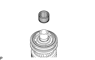
Remove the input shaft bearing from the input shaft.
-
-
REMOVE NO. 4 SYNCHRONIZER RING
-
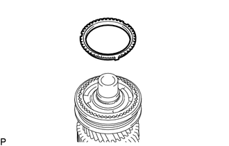
Remove the No. 4 synchronizer ring from the input shaft.
-
-
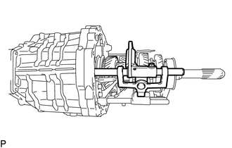
REMOVE INPUT SHAFT
-
Remove the input shaft from SST.
-
-
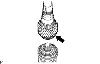
REMOVE COUNTER GEAR
-
Remove the counter gear from SST.
-
-
REMOVE REAR COUNTER GEAR BEARING OR ROLLER
-
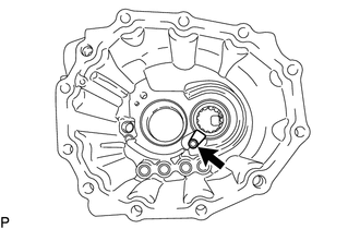
Remove the bolt and bearing lock plate.
-
*a Groove of the Rear Transmission Case Using SST, remove the rear counter gear bearing or roller (outer) from the rear transmission case.
- SST
- 09308-00010
Note
Do not damage the contact surfaces of the rear transmission case.
Tech Tips
Align the groove of the rear transmission case with the claws of SST.
-
-
REMOVE FRONT OUTPUT SHAFT BEARING
-
*a Groove of the Rear Transmission Case Using SST, remove the front output shaft bearing (outer race) from the rear transmission case.
- SST
- 09308-00010
Note
Do not damage the contact surfaces of the rear transmission case.
Tech Tips
Align the groove of the rear transmission case with the claws of SST.
-
-
REMOVE REAR OUTPUT SHAFT BEARING
-
*a Groove of the Rear Transmission Case Using SST, remove the rear output shaft bearing (outer) from the rear transmission case.
- SST
- 09308-00010
Note
Do not damage the contact surfaces of the rear transmission case.
Tech Tips
Align the groove of the rear transmission case with the claws of SST.
-
-
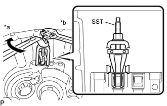
REMOVE SHIFT AND SELECT LEVER SHAFT NEEDLE ROLLER BEARING
-
*a Turn *b Hold Using SST, remove the shift and select lever shaft needle roller bearing from the rear transmission case sub-assembly.
- SST
- 09319-60020
-
-
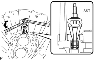
REMOVE SHIFT FORK SHAFT BEARING
-
*a Turn *b Hold Using SST, remove the 2 shift fork shaft bearings (rear side) from the rear transmission case sub-assembly.
- SST
- 09319-60020
-
-
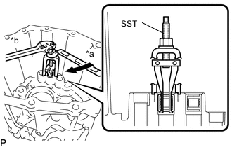
REMOVE SHIFT AND SELECT LEVER SHAFT NEEDLE ROLLER BEARING
-
*a Turn *b Hold Using SST, remove the shift and select lever shaft needle roller bearing (front side) from the front transmission case sub-assembly.
- SST
- 09319-60020
-
-
REMOVE SHIFT FORK SHAFT BEARING
-
*a Turn *b Hold Using SST, remove the 2 shift fork shaft bearings (front side) from the front transmission case sub-assembly.
- SST
- 09319-60020
-
-
REMOVE SHIFT AND SELECT LEVER SHAFT
-
Using a snap ring expander, remove the e-ring from the shift and select lever shaft.
-
Remove the bolt from the inner select lever.
-
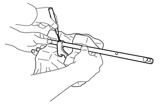
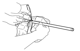
Using a 5 mm pin punch and hammer, tap out the straight pin.
-
Remove the shift interlock plate sub-assembly and inner select lever (shift and select cam, No. 2 lock ball pin and select return No. 1 compression spring) from the shift and select lever shaft.
-
Remove the shift and select cam, No. 2 lack ball pin, select return No. 1 compression spring from the inner select lever.
-
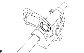
Using 2 screwdrivers and a hammer, tap off the snap ring.
Tech Tips
Use a piece of cloth to prevent the snap ring from flying off.
-
Remove the shift arm pivot and shift arm together with the needle roller bearing from the shift interlock plate sub-assembly.
-
-
REMOVE NEEDLE ROLLER BEARING
-
*1 Needle Roller Bearing *2 Shift Arm Using SST and a press, remove the needle roller bearing from the shift arm.
- SST
- 09950-60010 ( 09951-00220 )
- 09950-70010 ( 09951-07100 )
- 09527-20011
-
-
REMOVE NO. 2 GEAR SHIFT FORK SHAFT
-
Remove the bolt and No. 2 gear shift fork from the No. 2 gear shift fork shaft.
-
Remove the No. 2 gear shift fork shaft from the No. 1 gear shift fork head.
-
Place a cloth on 2 V-blocks, set the No. 2 gear shift fork shaft on the cloth, and then hold the shaft in place as shown in the illustration.
CAUTION:
-
Perform this procedure with 2 people.
-
Make sure to protect the gear shift fork shaft with a cloth before performing this procedure. If the gear shift fork shaft is damaged, shifting operations will worsen.
-
Firmly secure the gear shift fork shaft.
-
-
Using a 5 mm pin punch and hammer, tap out the slotted pin.
-
Remove the No. 2 gear shift head from the No. 2 gear shift fork shaft.
-
-
REMOVE NO. 4 GEAR SHIFT FORK SHAFT
-
Remove the No. 4 gear shift fork from the No. 4 gear shift fork shaft.
-
Place a cloth on 2 V-blocks, set the No. 4 gear shift fork shaft on the cloth, and then hold the shaft in place as shown in the illustration.
CAUTION:
-
Perform this procedure with 2 people.
-
Make sure to protect the gear shift fork shaft with a cloth before performing this procedure. If the gear shift fork shaft is damaged, shifting operations will worsen.
-
Firmly secure the gear shift fork shaft.
-
-
Using a 5 mm pin punch and hammer, tap out the slotted pin.
-
Remove the No. 4 gear shift head from the No. 4 gear shift fork shaft.
-
-
REMOVE NO. 1 GEAR SHIFT FORK SHAFT
-
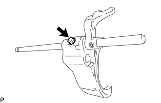
Remove the bolt and No. 1 gear shift fork from the No. 1 gear shift fork shaft.
-
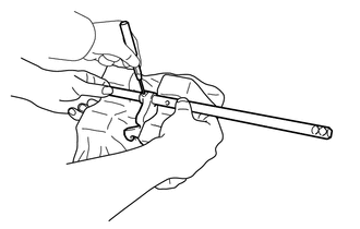
Place a cloth on 2 V-blocks, set the No. 1 gear shift fork shaft on the cloth, and then hold the shaft in place as shown in the illustration.
CAUTION:
-
Perform this procedure with 2 people.
-
Make sure to protect the gear shift fork shaft with a cloth before performing this procedure. If the gear shift fork shaft is damaged, shifting operations will worsen.
-
Firmly secure the gear shift fork shaft.
-
-
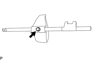
Using a 5 mm pin punch and hammer, tap out the slotted pin.
-
Remove the No. 1 gear shift head from the No. 1 gear shift fork shaft.
-
-
REMOVE NO. 3 GEAR SHIFT FORK SHAFT
-
Remove the bolt and No. 3 gear shift fork from the No. 3 gear shift fork shaft.
-