ВЫХОДНОЙ ВАЛ ПРОВЕРКА

PROCEDURE
-
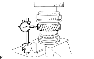
INSPECT 1ST GEAR THRUST CLEARANCE
-
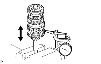
Using a dial indicator, measure the thrust clearance.
Standard clearance 0.30 to 0.55 mm (0.0119 to 0.0216 in.) If the clearance is not as specified, replace the No. 1 synchronizer ring set.
-
-
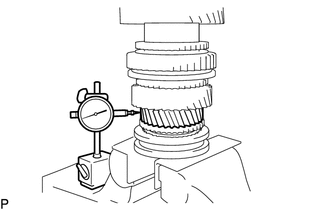
INSPECT 2ND GEAR THRUST CLEARANCE
-
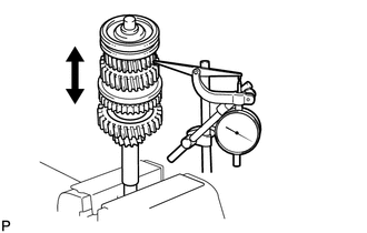
Using a dial indicator, measure the thrust clearance.
Standard clearance 0.10 to 0.25 mm (0.00394 to 0.00984 in.) If the clearance is not as specified, replace the No. 1 synchronizer ring set.
-
-
INSPECT 3RD GEAR THRUST CLEARANCE
-
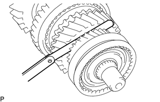
Using a feeler gauge, measure the thrust clearance.
Standard clearance 0.10 to 0.25 mm (0.00394 to 0.00984 in.) If the clearance is not as specified, replace the No. 2 synchronizer ring set.
-
-
INSPECT 1ST GEAR RADIAL CLEARANCE
-
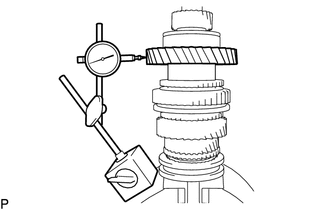
Using a dial indicator, measure the radial clearance.
Standard clearance 0.020 to 0.073 mm (0.000788 to 0.00287 in.) If the clearance is not as specified, replace the 1st gear needle roller bearing.
-
-
INSPECT 2ND GEAR RADIAL CLEARANCE
-
Using a dial indicator, measure the radial clearance.
Standard clearance 0.015 to 0.068 mm (0.000591 to 0.00267 in.) If the clearance is not as specified, replace the 2nd gear needle roller bearing.
-
-
INSPECT 3RD GEAR RADIAL CLEARANCE
-
Using a dial indicator, measure the radial clearance.
Standard clearance 0.015 to 0.068 mm (0.000591 to 0.00267 in.) If the clearance is not as specified, replace the 3rd gear needle roller bearing.
-
-
INSPECT OUTPUT SHAFT
-
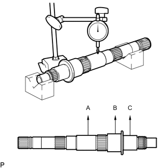
Using a dial indicator, measure the output shaft at point A, B and C shown in the illustration, and measure the runout of the output shaft.
Maximum runout 0.03 mm (0.00118 in.) If the runout is more than the maximum, replace the output shaft.
-
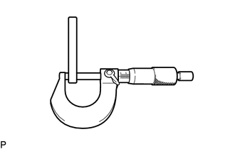
Using a micrometer, measure the journal diameter of the output shaft journal surface.
Standard Outside Diameter Item Specified Condition Journal A 38.979 to 38.995 mm (1.5347 to 1.5352 in.) Journal B 46.984 to 47.000 mm (1.8498 to 1.8503 in.) Journal C 37.984 to 38.000 mm (1.4955 to 1.4960 in.) If the outside diameter is not as specified, replace the output shaft.
-
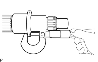
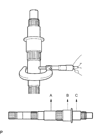
Using a micrometer, measure the thickness of the output shaft flange as shown in the illustration.
Standard thickness 4.8 to 5.2 mm (0.189 to 0.204 in.) If the thickness is not as specified, replace the output shaft.
-
-
INSPECT 3RD GEAR
-
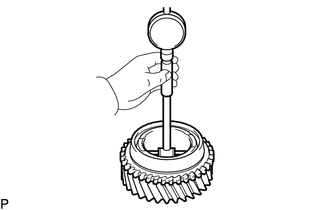
Using a cylinder gauge, measure the inside diameter of the 3rd gear.
Standard inside diameter 44.015 to 44.040 mm (1.7329 to 1.7338 in.) Maximum inside diameter 44.040 mm (1.7338 in.) If the inside diameter is more than the maximum, replace the 3rd gear.
-
-
INSPECT 2ND GEAR
-
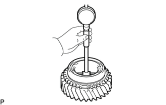
Using a cylinder gauge, measure the inside diameter of the 2nd gear.
Standard inside diameter 53.015 to 53.040 mm (2.0873 to 2.0881 in.) Maximum inside diameter 53.040 mm (2.0881 in.) If the inside diameter is more than the maximum, replace the 2nd gear.
-
-
INSPECT 1ST GEAR
-
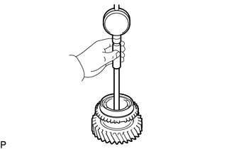
Using a cylinder gauge, measure the inside diameter of the 1st gear.
Standard inside diameter 46.015 to 46.040 mm (1.8117 to 1.8125 in.) Maximum inside diameter 46.040 mm (1.8125 in.) If the inside diameter is more than the maximum, replace the 1st gear.
-
-
INSPECT 1ST GEAR THRUST WASHER
-
Using a micrometer, measure the thickness of the thrust washer.
Standard thickness 5.95 to 6.05 mm (0.235 to 0.238 in.) Minimum thickness 5.95 mm (0.235 in.) If the thickness is less than the minimum, replace the 1st gear thrust washer.
-
-
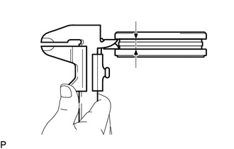
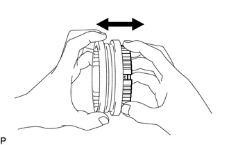
INSPECT NO. 1 SYNCHRONIZER RING SET (FOR 1ST GEAR)
-
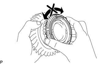
Apply gear oil to the cone of the 1st gear, and check that it does not turn in either direction while pushing the No. 1 synchronizer ring set.
If it turns, replace the No. 1 synchronizer ring set.
-
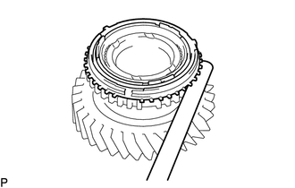
Measure the clearance between the No. 1 synchronizer ring and 1st gear while pushing the No. 1 synchronizer ring against the cone of the 1st gear.
Standard clearance 0.65 to 1.75 mm (0.0256 to 0.0688 in.) If the clearance is not as specified, replace the No. 1 synchronizer ring set.
-
-
INSPECT NO. 1 SYNCHRONIZER RING SET (FOR 2ND GEAR)
-
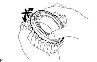
Apply gear oil to the cone of the 2nd gear, and check that it does not turn in either direction while pushing the No. 1 synchronizer ring set.
If it can turn, replace the No. 1 synchronizer ring set.
-
Push the No. 1 synchronizer ring set against the cone of the 2nd gear. Measure the clearance between the No. 1 synchronizer ring set and 2nd gear.
Standard clearance 0.65 to 1.75 mm (0.0256 to 0.0688 in.) If the clearance is not as specified, replace the No. 1 synchronizer ring set.
-
-
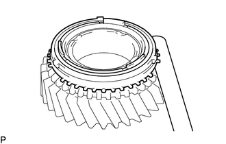
INSPECT NO. 2 SYNCHRONIZER RING SET (FOR 3RD GEAR)
-
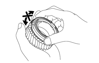
Apply gear oil to the cone of the 3rd gear, and check that it does not turn in either direction while pushing the No. 2 synchronizer ring set (for the 3rd gear).
If it can turn, replace the No. 2 synchronizer ring set.
-
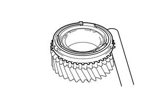
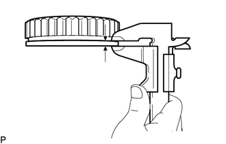
Push the No. 2 synchronizer ring set against the cone of the 3rd gear. Measure the clearance between the No. 2 synchronizer ring (for the 3rd gear) and 3rd gear.
Standard clearance 0.65 to 1.75 mm (0.0256 to 0.0689 in.) If the clearance is not as specified, replace the No. 2 synchronizer ring set.
-
-
INSPECT REVERSE GEAR
-
Using a vernier caliper, measure the thickness of reverse gear.
Standard thickness 4.95 to 5.05 mm (0.195 to 0.198 in.) If the groove is not as specified, replace the reverse gear.
-
-
INSPECT NO. 1 TRANSMISSION CLUTCH HUB
-

Check the sliding condition between the No. 1 clutch hub and the reverse gear.
-
Check the internal spline of the reverse gear for wear.
If there are any defects, replace the reverse gear.
-
Check the external spline of the clutch hub for wear.
If there are any defects, replace the No. 1 transmission clutch hub.
-
-
INSPECT NO. 2 TRANSMISSION HUB SLEEVE
-
Using a vernier caliper, measure the No. 2 hub sleeve groove.
Standard groove 10.15 to 10.25 mm (0.400 to 0.403 in.) If the groove is not as specified, replace the No. 2 transmission hub sleeve.
-
-
INSPECT NO. 2 TRANSMISSION CLUTCH HUB
-
Check the sliding condition between the No. 2 transmission clutch hub and No. 2 hub sleeve.
-
Check the internal spline of the No. 2 hub sleeve for wear.
If there are any defects, replace the No. 2 hub sleeve.
-
Check the external spline of the No. 2 transmission clutch hub for wear.
If there are any defects, replace the No. 2 transmission clutch hub.
-