БЛОК МЕХАНИЧЕСКОЙ ТРАНСМИССИИ ПОВТОРНАЯ СБОРКА

PROCEDURE
-
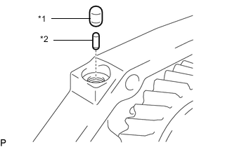
INSTALL STRAIGHT PIN AND RING PIN
Note
It is not necessary to remove a straight pin and ring pin unless it is being replaced.
-
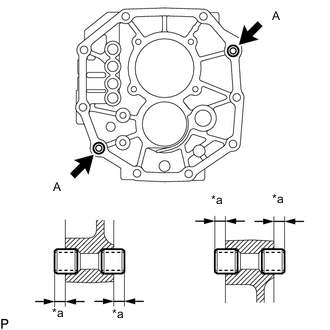
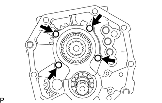
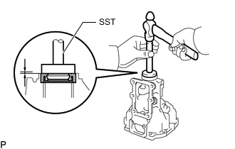
*a Protrusion Height Using a plastic-faced hammer, tap 4 new ring pins into the intermediate plate.
Specified Condition Item Specified Condition A 5.5 to 7.5 mm (0.217 to 0.295 in.) -
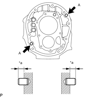
*a Protrusion Height Using a plastic-faced hammer, tap 2 new straight pins into the transmission case.
Specified Condition Item Specified Condition A 9.0 to 11.0 mm (0.355 to 0.433 in.)
-
-
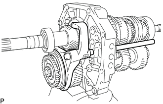
INSTALL OUTPUT SHAFT
-
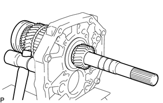
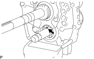
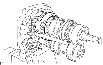
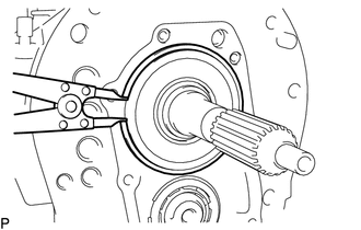
Apply gear oil to the sliding part of the output shaft.
-
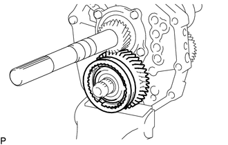
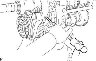
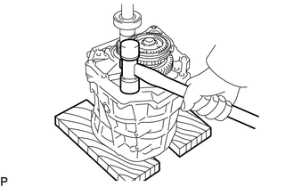
Using a plastic-faced hammer, install the output shaft by tapping the intermediate plate.
-
-
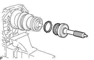
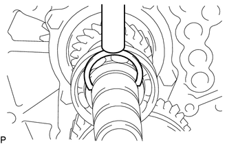
INSTALL OUTPUT SHAFT BEARING SHAFT SNAP RING
-
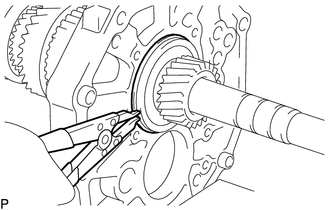
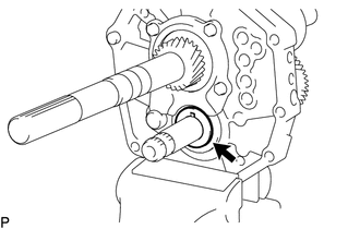
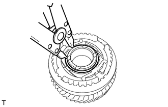
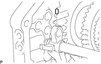
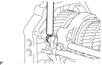
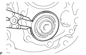
Using a snap ring expander, install the output shaft bearing shaft snap ring to the output shaft.
-
-
INSPECT NO. 2 SYNCHRONIZER RING
-
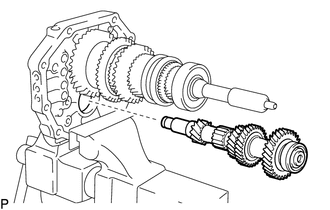
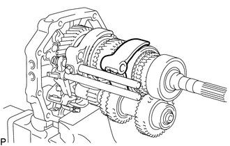
INSTALL INPUT SHAFT
-
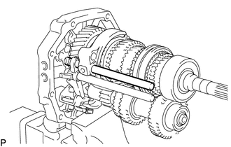
Apply gear oil to the input shaft and No. 2 synchronizer ring, and install them to the output shaft.
Note
-
When installing the input shaft to the output shaft, align the protrusion of the No. 2 synchronizer ring with the cutout of the transmission clutch hub.
-
Check that the input shaft rotates slightly.
-
-
-
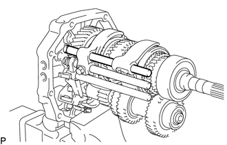
INSTALL COUNTER GEAR
-
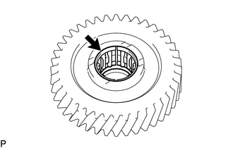
Temporarily install the counter gear to the intermediate plate.
-
-
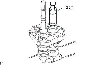
INSTALL COUNTER SHAFT REAR BEARING
-
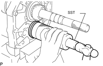
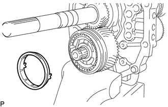
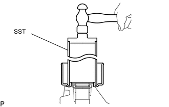
Using SST and a hammer, tap in a new counter shaft rear bearing to the intermediate plate.
- SST
- 09316-60011 ( 09316-00011 )
Tech Tips
Install the counter shaft rear bearing while tapping the tip of the counter gear with a plastic-faced hammer so that the counter gear does not hit the side wall of the output shaft gear by being pushed forward.
-
-
INSTALL REVERSE IDLER GEAR SUB-ASSEMBLY
-
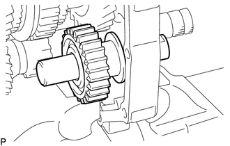
Apply gear oil to each sliding part of the reverse idler gear sub-assembly and the reverse idler gear shaft, and install the reverse idler gear sub-assembly and reverse idler shaft to the intermediate plate.
Note
Install the reverse idler shaft with its groove facing the rear side, and install it from the rear side.
-
-
INSTALL OUTPUT SHAFT REAR BEARING RETAINER
-
Insert the output shaft rear bearing retainer into the groove of the reverse idler gear shaft and install it with the 4 bolts.
- Torque:
- 18 N*m { 184 kgf*cm, 13 ft.*lbf }
-
-
INSTALL 5TH GEAR THRUST WASHER PIN
-
Apply MP grease to the 5th gear thrust washer pin, and install it to the counter gear.
-
-
INSTALL 5TH GEAR THRUST WASHER
-
Apply gear oil to the 5th gear thrust washer, and install it to the counter gear.
Note
Install the 5th gear thrust washer so that its chamfer side faces forward.
-
-
INSTALL NO. 3 SYNCHROMESH SHIFTING KEY
-
Apply gear oil to the sliding part of the No. 3 transmission hub sleeve, and install the hub sleeve to the counter 5th gear.
Note
Make sure that the No. 3 transmission hub sleeve and counter 5th gear are installed facing the correct direction.
-
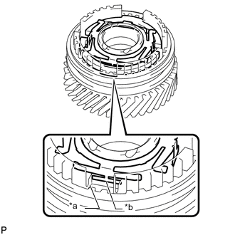
*a Cutout *b Protrusion Install the 2 No. 3 synchromesh shifting keys and No. 3 synchromesh shifting key spring to the counter 5th gear as shown in the illustration.
Tech Tips
When installing the No. 3 synchromesh shifting key spring, make sure the protrusion fits into the cutout.
-
Using a snap ring expander, install the shaft snap ring to the counter 5th gear.
-
-
INSTALL COUNTER 5TH GEAR BEARING
-
Apply gear oil to the counter 5th gear bearing and install it to the countershaft 5th gear.
-
-
INSTALL COUNTERSHAFT 5TH GEAR
-
Apply gear oil to the countershaft 5th gear and No. 3 transmission hub sleeve, and install them to the countershaft.
-
-
INSTALL NO. 3 SYNCHRONIZER RING
-
Apply gear oil to the No. 3 synchronizer ring, and install it to the countershaft 5th gear.
Note
Install the No. 3 synchronizer ring so that its protrusion fits between the 2 synchromesh shifting keys.
-
-
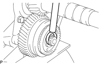
INSTALL NO. 5 GEAR SPLINE PIECE
-
Using SST and a press, press in the No. 5 gear spline piece to the countershaft 5th gear.
- SST
- 09316-60011 ( 09316-00011 )
Note
Check that the gear rotates freely.
-
-
INSTALL COUNTER SHAFT REAR SNAP RING
-
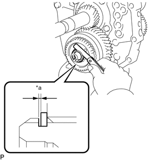
*a Thrust Clearance Select a snap ring so that the thrust clearance between the No. 5 gear spline piece and snap ring is within the specification.
Standard clearance 0.10 mm (0.00393 in.) or less Snap Ring Thickness Thickness 2.80 to 2.85 mm (0.111 to 0.112 in.) 2.85 to 2.90 mm (0.113 to 0.114 in.) 2.90 to 2.95 mm (0.115 to 0.116 in.) 2.95 to 3.00 mm (0.117 to 0.118 in.) 3.00 to 3.05 mm (0.119 to 0.120 in.) 3.05 to 3.10 mm (0.121 to 0.122 in.) 3.10 to 3.15 mm (0.123 to 0.124 in.) -
Using a brass bar and hammer, install the snap ring.
-
-
INSPECT COUNTERSHAFT 5TH GEAR THRUST CLEARANCE
-
INSPECT COUNTERSHAFT 5TH GEAR RADIAL CLEARANCE
-
INSTALL OUTPUT SHAFT REAR BEARING
-
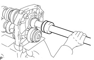
Using SST and a press, press in the spacer and a new output shaft rear bearing to the output shaft.
- SST
- 09309-35010
-
Select a shaft snap ring so that the thrust clearance between the output shaft rear bearing and shaft snap ring is within the specification.
Standard clearance 0.10 mm (0.00393 in.) or less Snap Ring Thickness Thickness Thickness 2.65 to 2.70 mm (0.105 to 0.106 in.) 3.10 to 3.15 mm (0.122 to 0.124 in.) 2.70 to 2.75 mm (0.107 to 0.108 in.) 3.15 to 3.20 mm (0.124 to 0.126 in.) 2.75 to 2.80 mm (0.109 to 0.110 in.) 3.20 to 3.25 mm (0.126 to 0.128 in.) 2.80 to 2.85 mm (0.111 to 0.112 in.) 3.25 to 3.30 mm (0.128 to 0.129 in.) 2.85 to 2.90 mm (0.113 to 0.114 in.) 3.30 to 3.35 mm (0.130 to 0.131 in.) 2.90 to 2.95 mm (0.115 to 0.116 in.) 3.35 to 3.40 mm (0.132 to 0.133 in.) 2.95 to 3.00 mm (0.117 to 0.118 in.) 3.40 to 3.45 mm (0.134 to 0.135 in.) 3.00 to 3.05 mm (0.119 to 0.120 in.) 3.45 to 3.50 mm (0.136 to 0.137 in.) 3.05 to 3.10 mm (0.121 to 0.122 in.) - -
Using a brass bar and hammer, install the output shaft bearing shaft snap ring.
-
-
INSTALL SPEEDOMETER DRIVE GEAR
-
Using snap ring pliers, install the snap ring.
-
Install the steel ball and speedmeter drive gear.
-
Using snap ring pliers, install the snap ring.
-
-
INSTALL REVERSE SHIFT ARM BRACKET
-
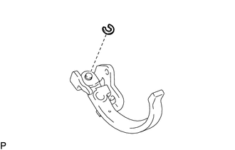
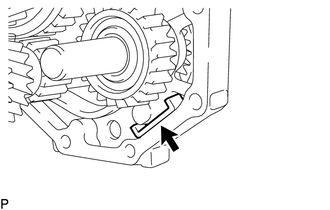
Install the reverse shift arm to the reverse shift arm bracket with a new snap ring.
-
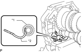
*1 Reverse Idler Gear *2 Reverse Shift Arm Insert the tip of the reverse shift arm into the reverse idler gear sub-assembly.
-
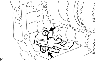
Install the reverse shift arm bracket with the 2 bolts.
- Torque:
- 18 N*m { 184 kgf*cm, 13 ft.*lbf }
-
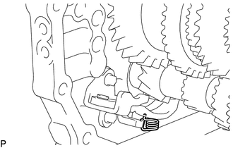
Install the torsion spring to the reverse shift arm bracket.
Note
Make sure that the torsion spring is securely installed to the reverse shift arm.
-
-
INSTALL REVERSE SHIFT FORK
-
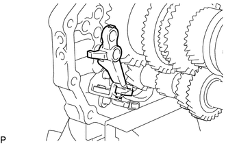
Install the reverse shift fork to the reverse shift arm.
-
-
INSTALL NO. 3 GEAR SHIFT FORK SHAFT
-
Install the No. 3 gear shift fork to the No. 3 transmission hub sleeve and No. 3 gear shift fork shaft to the intermediate plate from the front side.
-
Install the No. 1 shift interlock roller to the reverse shift fork.
-
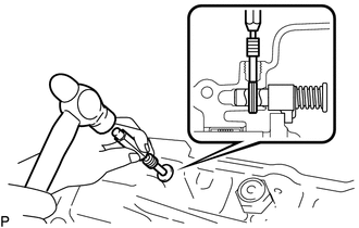
Using a brass bar and hammer, install the shift fork shaft snap ring to the No. 3 gear shift fork shaft.
-
Using a 5 mm pin punch and hammer, install the shift fork set slotted spring pin to the No. 3 gear shift fork.
-
-
INSTALL NO. 1 GEAR SHIFT FORK SHAFT
-
Install the No. 1 shift interlock roller to the intermediate plate.
-
Install the No. 1 gear shift fork to the reverse gear.
-
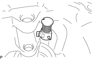
Install the No. 1 gear shift fork shaft to the intermediate plate from the rear side.
-
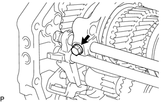
Install a new bolt to the No. 1 gear shift fork shaft.
- Torque:
- 19.5 N*m { 199 kgf*cm, 14 ft.*lbf }
-
Using a brass bar and hammer, install the shift fork shaft snap ring to the No. 1 gear shift fork shaft.
-
-
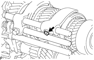
INSTALL NO. 2 GEAR SHIFT FORK SHAFT
-
*1 No. 1 Shift Interlock Roller *2 Shift Interlock Pin Install the shift interlock pin and No. 1 shift interlock roller to the intermediate plate.
-
Install the No. 2 gear shift fork to the No. 2 transmission hub sleeve.
-
Apply gear oil to the No. 2 gear shift fork shaft, and install the No. 2 gear shift fork shaft to the intermediate plate from the rear side.
-
Install a new bolt to the No. 2 gear shift fork.
- Torque:
- 19.5 N*m { 199 kgf*cm, 14 ft.*lbf }
-
Using a brass bar and hammer, install the shift fork shaft snap ring to the No. 2 gear shift fork shaft.
-
-
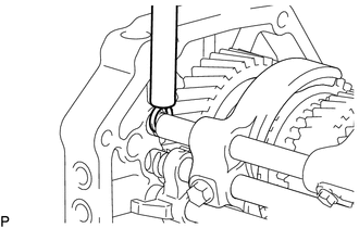
INSTALL SHIFT DETENT BALL PLUG
-
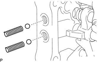
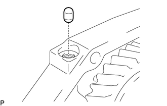
Install 2 new shift detent ball compression springs and 2 shift detent balls to the intermediate plate.
-
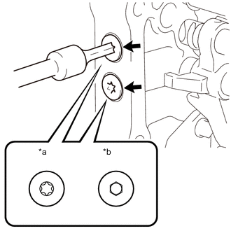
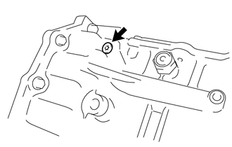
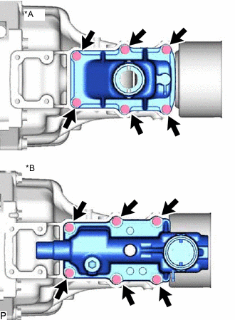
*a for Type A *b for Type B Install 2 new shift detent ball plugs to the intermediate plate.
-
for Type A:
Using a T40 ''TORX'' socket wrench, install 2 new shift detent ball plugs to the intermediate plate.
- Torque:
- 18.5 N*m { 189 kgf*cm, 14 ft.*lbf }
-
for Type B
Using a 6 mm hexagon socket wrench, install 2 new shift detent ball plugs to the intermediate plate.
- Torque:
- 18.5 N*m { 189 kgf*cm, 14 ft.*lbf }
-
-
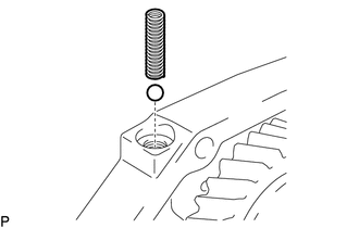
Install the shift detent ball and shift detent ball compression spring to the intermediate plate.
-
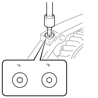
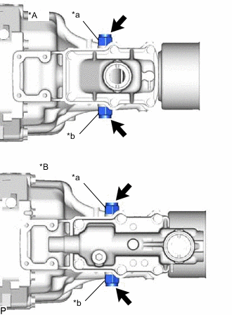
*a for Type A *b for Type B Install a new shift detent ball plug to the intermediate plate.
-
for Type A:
Using a T40 ''TORX'' socket wrench, install a new shift detent ball plug to the intermediate plate.
- Torque:
- 18.5 N*m { 189 kgf*cm, 14 ft.*lbf }
-
for Type B
Using a 6 mm hexagon socket wrench, install a new shift detent ball plug to the intermediate plate.
- Torque:
- 18.5 N*m { 189 kgf*cm, 14 ft.*lbf }
-
-
-
INSTALL TRANSMISSION MAGNET
-
Clean the transmission magnet, and install it to the intermediate plate.
-
-
INSTALL MANUAL TRANSMISSION CASE
-
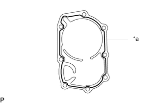
*1 Seal Packing Apply seal packing to the manual transmission case as shown in the illustration.
Seal packing Toyota Genuine Seal Packing 1281, Three Bond 1281 or equivalent -
Using a plastic-faced hammer, tap the manual transmission case to attach it to the intermediate plate.
-
-
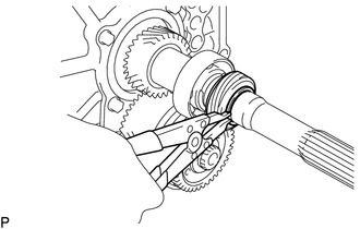
INSTALL COUNTER GEAR FRONT BEARING SNAP RING
-
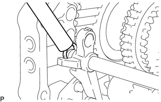
Using a snap ring expander, install the counter gear front bearing snap ring to the manual transmission case.
-
-
INSTALL FRONT BEARING SHAFT SNAP RING
-
Using a snap ring expander, install the front bearing shaft snap ring to the manual transmission case.
-
-
INSTALL TRANSMISSION FRONT BEARING RETAINER OIL SEAL
-
INSTALL FRONT BEARING RETAINER
-
Clean and degrease the contact surface of the front bearing retainer and manual transmission case.
-
Clean and degrease the 8 bolts and the installation holes in the manual transmission case.
-
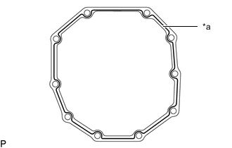
*1 Seal Packing Apply seal packing to the front bearing retainer as shown in the illustration.
Seal packing Toyota Genuine Seal Packing 1281, Three Bond 1281 or equivalent Note
-
Assemble the parts within 10 minutes of application. Otherwise, the seal packing material must be removed and reapplied.
-
Apply seal packing in a continuous line (width 1.2 mm (0.0472 in.)) along the sealing surface of the manual transmission case
-
-
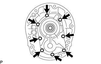
Install the front bearing retainer to the manual transmission case with 8 new bolts.
- Torque:
- 16.5 N*m { 168 kgf*cm, 12 ft.*lbf }
-
Check that the input shaft and output shaft rotate smoothly.
-
-
INSTALL MANUAL TRANSMISSION EXTENSION HOUSING OIL SEAL
-
Using SST and a hammer, tap in a new manual transmission extension housing oil seal to the extension housing sub-assembly.
- SST
- 09710-30050
- 09950-70010 ( 09951-07100 )
Standard depth -0.5 to 0.5 mm (-0.196 to 0.196 in.) Note
Be careful not to damage the oil seal lip.
-
Lightly apply MP grease to the lip of the manual transmission extension housing oil seal.
-
-
INSTALL REVERSE RESTRICT PIN
-
Install the reverse restrict pin to the extension housing sub-assembly.
-
Using a 5 mm pin punch and hammer, tap in the slotted pin to the extension housing sub-assembly.
-
Using a T40 ''TORX'' socket wrench, install a new plug to the transfer adapter sub-assembly.
- Torque:
- 18.5 N*m { 189 kgf*cm, 14 ft.*lbf }
-
-
INSTALL NO. 1 EXTENSION HOUSING OIL RECEIVER PIPE
-
Install the No. 1 extension housing oil receiver pipe with the bolt.
- Torque:
- 11 N*m { 112 kgf*cm, 8 ft.*lbf }
-
-
INSTALL NO. 2 EXTENSION HOUSING OIL RECEIVER PIPE
-
Install the No. 2 extension housing oil receiver pipe to the extension housing sub-assembly.
-
-
INSTALL EXTENSION HOUSING DUST DEFLECTOR
-
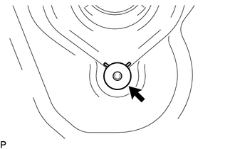
Using SST and a hammer, tap in the extension housing dust deflector.
- SST
- 09513-36040
-
-
INSTALL EXTENSION HOUSING SUB-ASSEMBLY
-
*1 Seal Packing Apply seal packing to the extension housing sub-assembly as shown in the illustration.
Seal packing Toyota Genuine Seal Packing 1281, Three Bond 1281 or equivalent -
Install the shift and select lever to the extension housing sub-assembly.
-
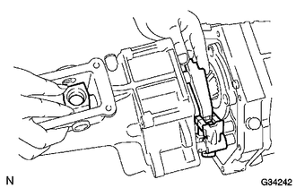
Connect the shift and select lever to the fork shaft and install the shift lever housing.
-
Align the shift and select lever with the extension housing sub-assembly installation hole and push into the extension housing sub-assembly.
-
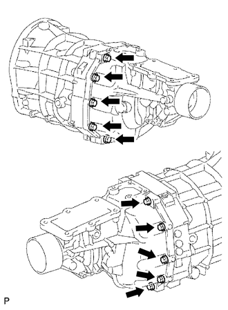
Install the extension housing sub-assembly to the manual transmission case with the 10 bolts.
- Torque:
- 37 N*m { 377 kgf*cm, 27 ft.*lbf }
-
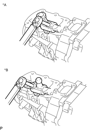
*A w/o Console Box Lid *B w/ Console Box Lid Install a new bolt to the shift lever housing.
- Torque:
- 33.3 N*m { 340 kgf*cm, 25 ft.*lbf }
-
-
INSTALL FLOOR SHIFT CONTROL SHIFT LEVER RETAINER SUB-ASSEMBLY
-
Install a new gasket and the floor shift control shift lever retainer sub-assembly.
-
*A w/o Console Box Lid *B w/ Console Box Lid Install the 6 bolts.
- Torque:
- 18 N*m { 184 kgf*cm, 13 ft.*lbf }
-
-
INSTALL REVERSE RESTRICT PIN ASSEMBLY
-
*A w/o Console Box Lid *B w/ Console Box Lid *a White *b Green Install the 2 reverse restrict pin assemblies.
- Torque:
- 37 N*m { 377 kgf*cm, 27 ft.*lbf }
-
-
INSTALL BACK-UP LIGHT SWITCH ASSEMBLY
-
INSTALL CLUTCH HOUSING
-
Clean the threads of the bolts and the manual transmission case with non-residue solvent.
-
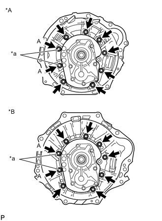
*A for 1TR-FE, 2TR-FE *B except 1TR-FE, 2TR-FE *a Precoated Bolt Install the clutch housing to the manual transmission case with the 7 bolts.
- Torque:
- 36 N*m { 367 kgf*cm, 27 ft.*lbf }
-
Install 2 new bolts (labeled A).
- Torque:
- 36 N*m { 367 kgf*cm, 27 ft.*lbf }
-
-
INSTALL RELEASE FORK SUPPORT
-
INSTALL CLUTCH RELEASE BEARING ASSEMBLY
-
INSTALL CLUTCH RELEASE FORK BOOT
-
INSTALL DRAIN PLUG SUB-ASSEMBLY
-
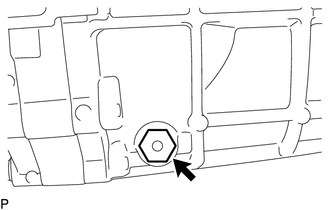
Install a new gasket and the drain plug sub-assembly to the manual transmission case.
- Torque:
- 37 N*m { 377 kgf*cm, 27 ft.*lbf }
-
-
INSTALL MANUAL TRANSMISSION FILLER PLUG
-
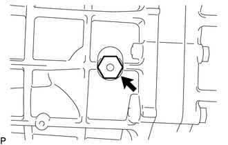
Install a new gasket and the manual transmission filler plug to the manual transmission case.
- Torque:
- 37 N*m { 377 kgf*cm, 27 ft.*lbf }
-