СИСТЕМА АВТОМАТИЧЕСКОЙ ТРАНСМИССИИ, Diagnostic DTC:U0100

| DTC Code | DTC Name |
|---|---|
| U0100 | Lost Communication with ECM / PCM "A" |
DESCRIPTION
The ECM communicates with the TCM using the Controller Area Network (CAN).
If there is a problem with this communication, the TCM stores a DTC.
| DTC No. | Detection Item | DTC Detection Condition | Trouble Area | MIL | Memory |
|---|---|---|---|---|---|
| U0100 | Lost Communication with ECM / PCM "A" | All conditions are met for 1.25 seconds (1-trip detection logic):
|
|
Comes on | DTC stored |
WIRING DIAGRAM
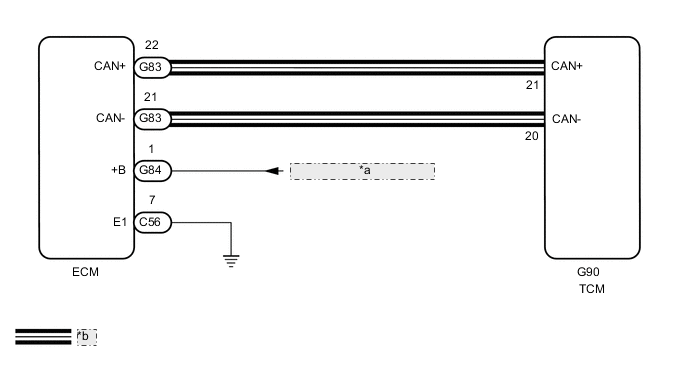
| *a | from EFI-MAIN NO. 1 Relay |
| *b | CAN Communication Line |
CAUTION / NOTICE / HINT
Tech Tips
-
Refer to the inspection procedure for the CAN communication system.
-
If the CAN communication malfunctions, the TCM cannot receive current data from the ECM. In this case, the freeze frame data output from the TCM has not been updated so the data will not be useful for the inspection. However, reading the Data List as the first step in troubleshooting is an effective way to find malfunctions.
-
The malfunctioning area can be confirmed using the Bus Check function of the GTS.
for LHD:
for RHD:
-
After the repair, clear the DTCs and perform the following procedure to check that DTCs are not output.
-
Check that the battery voltage is 10.5 V or higher.
-
Turn the ignition switch to ON.
-
Check for DTCs again.
PROCEDURE
-
CHECK TERMINAL VOLTAGE (POWER SOURCE OF ECM)
-
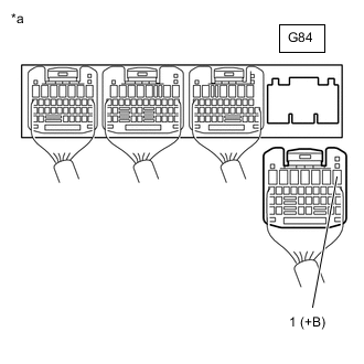
*a Rear view of wire harness connector
(to ECM)
Disconnect the ECM connector.
-
Turn the ignition switch to ON.
-
Measure the voltage according to the value(s) in the table below.
Standard Voltage Tester Connection Condition Specified Condition G84-1 (+B) - Body ground Ignition switch ON 11 to 14 V Result Proceed to OK NG
NG 
GO TO ECM POWER SOURCE CIRCUIT Click here
OK 
-
-
CHECK HARNESS AND CONNECTOR (ECM - BODY GROUND)
-
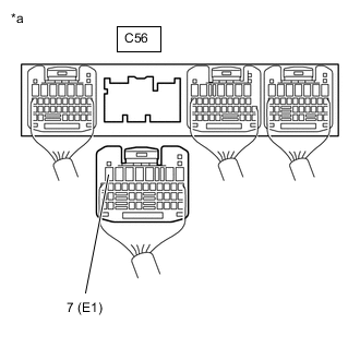
*a Rear view of wire harness connector
(to ECM)
Disconnect the ECM connector.
-
Measure the resistance according to the value(s) in the table below.
Standard Resistance Tester Connection Condition Specified Condition C56-7 (E1) - Body ground Always Below 1 Ω Result Proceed to OK NG
NG
REPAIR OR REPLACE HARNESS OR CONNECTOR
OK
-
-
CHECK HARNESS AND CONNECTOR (ECM - TCM)
-
Disconnect the G83 ECM connector.
-
Disconnect the G90 TCM connector.
-
Measure the resistance according to the value(s) in the table below.
Standard Resistance Tester Connection Condition Specified Condition G83-22 (CAN+) - G90-21 (CAN+) Always Below 1 Ω G83-21 (CAN-) - G90-20 (CAN-) Always Below 1 Ω G83-22 (CAN+) or G90-21 (CAN+) - Body ground or other terminals Always 10 kΩ or higher G83-21 (CAN-) or G90-20 (CAN-) - Body ground or other terminals Always 10 kΩ or higher Result Proceed to OK NG
NG
REPAIR OR REPLACE HARNESS OR CONNECTOR
OK
-
-
REPLACE TCM
-
Replace the TCM.
Result Proceed to NEXT
NEXT
-
-
CHECK DTC OUTPUT
-
Connect the GTS to the DLC3.
-
Turn the ignition switch to ON.
-
Turn the GTS on.
-
Clear the DTCs.
Powertrain > ECT > Clear DTCs -
Start the engine.
-
Enter the following menus: Powertrain / ECT / Trouble Codes.
Powertrain > ECT > Trouble Codes -
Read the DTCs using the GTS.
Result Result Proceed to DTCs are not output A U0100 is output B
A
END
B
REPLACE ECM Click here
-