МАСЛЯНЫЙ НАСОС УСТАНОВКА

PROCEDURE
-
INSTALL TIMING CHAIN CASE OIL SEAL
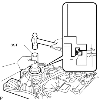
*a No Clearance
-
Using SST and a hammer, tap in a new timing chain case oil seal until its surface is flush with the edge of the timing chain cover sub-assembly.
- SST
- 09223-75010 ( 09951-07100 )
Note
-
Keep the lip free from foreign matter.
-
Do not tap the timing chain case oil seal at an angle.
-
Apply MP grease to the lip of the timing chain case oil seal.
-
-
INSTALL ENGINE WATER PUMP ASSEMBLY
-
Install a new gasket and the engine water pump assembly with the 8 bolts.
- Torque:
- 13 N*m { 133 kgf*cm, 10 ft.*lbf }
-
-
INSTALL TIMING CHAIN COVER SUB-ASSEMBLY
-
Install 3 new O-rings to the timing chain cover sub-assembly.
-
Clean and degrease the contact surfaces of the timing chain cover sub-assembly, cylinder head sub-assembly and cylinder block sub-assembly.
-
Apply seal packing to the timing chain cover sub-assembly in a continuous line as shown in the following illustration.
Seal packing Toyota Genuine Seal Packing Black, Three Bond 1207B or equivalent 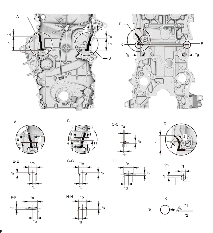
*1 Cylinder Head Sub-assembly *2 Cylinder Block Sub-assembly *a 2.0 mm (0.0787 in.) *b 2.5 mm (0.0984 in.) *c 5.0 mm (0.197 in.) *d 6.0 mm (0.236 in.) *e 7.0 mm (0.276 in.) *f 8.0 mm (0.315 in.) or more *g 20 mm (0.787 in.) *h 54 mm (2.13 in.) *i 56.5 mm (2.22 in.) *j 58 mm (2.28 in.) *k 2.5 to 4.0 mm (0.0984 to 0.157 in.) *l 5.0 to 6.0 mm (0.197 to 0.236 in.) *m 9.0 to 13 mm (0.354 to 0.512 in.) *n 10 to 14 mm (0.394 to 0.551 in.) *o 12 to 16 mm (0.472 to 0.630 in.) *p Seal Packing Note
-
Remove any oil from the contact surface.
-
When the contact surfaces are wet, wipe them with an oil-free cloth before applying seal packing.
-
Install the timing chain cover sub-assembly within 3 minutes and tighten the bolts within 10 minutes after applying seal packing.
-
Do not start the engine for at least 4 hours after the installation.
-
-
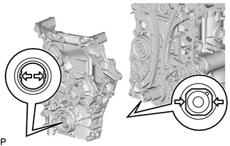
Align the width of the joint portion of the oil pump drive rotor and the crankshaft timing gear, and then install the timing chain cover sub-assembly.
-
Temporarily install the timing chain cover sub-assembly with the 16 bolts and nut.
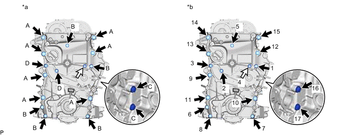
*a Types of nut and bolt *b Tightening order 
Bolt 
Nut - Torque:
- for bolt A
- 57 N*m { 581 kgf*cm, 42 ft.*lbf }
- for bolt B and nut
- 23 N*m { 235 kgf*cm, 17 ft.*lbf }
- for bolt C
- 21 N*m { 214 kgf*cm, 15 ft.*lbf }
- for bolt D
- 25 N*m { 255 kgf*cm, 18 ft.*lbf }
Bolt Length Item Length Thread Diameter Bolt A 75 mm (2.95 in.) 10 mm (0.394 in.) Bolt B 75 mm (2.95 in.) 8.0 mm (0.315 in.) Bolt C 40 mm (1.57 in.) 8.0 mm (0.315 in.) Bolt D 90 mm (3.54 in.) 8.0 mm (0.315 in.) Note
-
Make sure that there is no oil on the threads of bolts.
-
Check the bolts and bolt holes, and clean and degrease them.
-
Remove the seal packing from the 2 bolt holes for the No. 1 compressor mounting bracket.
Note
Do not use any cleaners to remove the seal packing.
-
-
INSTALL CRANKSHAFT POSITION SENSOR
-
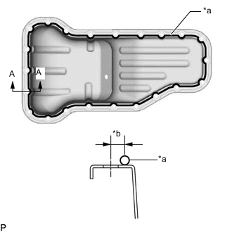
INSTALL OIL PAN SUB-ASSEMBLY
-
Clean and degrease the contact surfaces of the oil pan sub-assembly and cylinder block sub-assembly.
-
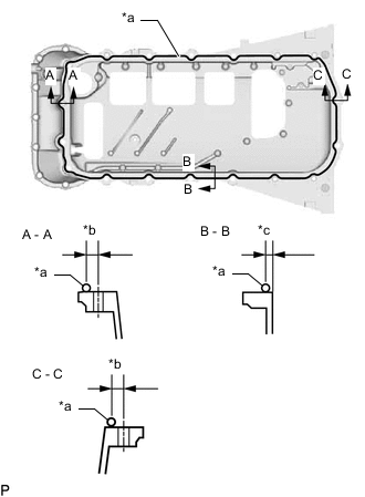
*a Seal Packing *b 8.0 mm (0.315 in.) *c 6.5 mm (0.256 in.) Apply seal packing in a continuous line as shown in the illustration.
Seal packing Toyota Genuine Seal Packing Black, Three Bond 1207B or equivalent Application Specification Area Seal Packing Diameter Distance from Edge of Cover or Center of Bolt Hole to Center of Seal Packing A - A and C - C 2.0 to 3.0 mm (0.0787 to 0.118 in.) 8.0 mm (0.315 in.) B - B 2.0 to 3.0 mm (0.0787 to 0.118 in.) 6.5 mm (0.256 in.) Note
-
Remove any oil from the contact surface.
-
Install the oil pan sub-assembly within 3 minutes and tighten the bolts within 10 minutes after applying seal packing.
-
Do not start the engine for at least 4 hours after the installation.
-
-
Bolt A Bolt B 
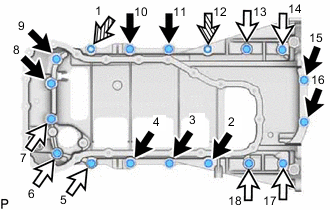
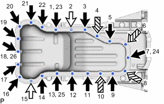
Nut Temporarily install the oil pan sub-assembly with the 16 bolts and 2 nuts.
Bolt Length Item Length Bolt A 20 mm (0.787 in.) Bolt B 40 mm (1.57 in.) -
Uniformly tighten the 16 bolts and 2 nuts in the order shown in the illustration.
- Torque:
- 26 N*m { 265 kgf*cm, 19 ft.*lbf }
-
-
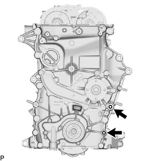
INSTALL OIL STRAINER SUB-ASSEMBLY
-
*a Protrusion *b Groove Install a new gasket to the oil strainer sub-assembly.
Tech Tips
Align the protrusion of the gasket with the groove of the oil strainer sub-assembly.
-
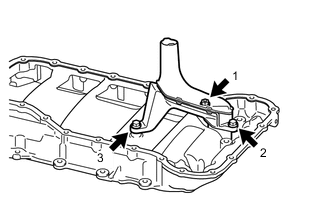
Install the oil strainer sub-assembly with the 2 bolts and nut in the sequence shown in the illustration.
- Torque:
- 10 N*m { 102 kgf*cm, 7 ft.*lbf }
-
-
INSTALL NO. 2 OIL PAN SUB-ASSEMBLY
-
Clean and degrease the contact surfaces of the oil pan sub-assembly and No. 2 oil pan sub-assembly.
-
*a Seal Packing *b 6.0 mm (0.236 in.) Apply seal packing in a continuous line as shown in the illustration.
Seal packing Toyota Genuine Seal Packing Black, Three Bond 1207B or equivalent Application Specification Seal Packing Diameter Distance from Center of Bolt Hole to Center of Seal Packing 2.5 to 3.5 mm (0.0984 to 0.138 in.) 6.0 mm (0.236 in.) Note
-
Remove any oil from the contact surface.
-
Install the No. 2 oil pan sub-assembly within 3 minutes and tighten the bolts within 10 minutes after applying seal packing.
-
Do not start the engine for at least 4 hours after the installation.
-
-
Temporarily install the No. 2 oil pan sub-assembly with the 16 bolts, 4 adjusting screws and 2 nuts.
-
Bolt Nut Adjusting Screw Uniformly tighten the 16 bolts, 4 adjusting screws and 2 nuts in the order shown in the illustration.
- Torque:
- 9.0 N*m { 92 kgf*cm, 80 in.*lbf }
-
Install a new gasket and the oil pan drain plug.
- Torque:
- 37.5 N*m { 382 kgf*cm, 28 ft.*lbf }
-
-
INSTALL OIL PAN COVER SILENCER
-
Install the oil pan cover silencer with the 4 No. 1 oil pan plugs.
- Torque:
- 7.0 N*m { 71 kgf*cm, 62 in.*lbf }
-
-
INSTALL CRANKSHAFT PULLEY
-
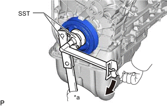
*a Hold Turn Align the key groove of the crankshaft pulley with the pulley set key and slide on the crankshaft pulley.
-
Using SST, install a new crankshaft pulley set bolt.
- SST
- 09213-54015 ( 91651-60855 )
- 09330-00021
- Torque:
- 260 N*m { 2651 kgf*cm, 192 ft.*lbf }
Note
Do not reuse the crankshaft pulley set bolt.
-
-
INSTALL CYLINDER HEAD COVER SUB-ASSEMBLY
-
Clean and degrease the contact surfaces of the timing chain cover sub-assembly, cylinder head and cylinder head cover sub-assembly.
-
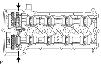
Seal Packing Application Area Apply seal packing as shown in the illustration.
Seal packing Toyota Genuine Seal Packing Black, Three Bond 1207B or equivalent Seal packing diameter 4.0 mm (0.157 in.) Note
-
Remove any oil from the contact surface.
-
Install the cylinder head cover sub-assembly within 3 minutes and tighten the bolts within 10 minutes after applying seal packing.
-
Do not add the engine oil for at least 4 hours after the installation.
-
Do not start the engine for at least 4 hours after the installation.
-
-
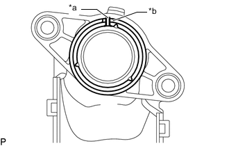
Install a new No. 1 camshaft bearing cap oil hole gasket to the cylinder head cover connector sub-assembly.
-
Install a new cylinder head cover gasket to the cylinder head cover sub-assembly.
-
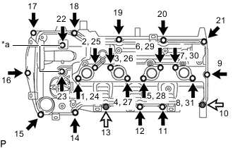
*a Plate Washer and Seal Washer Bolt Nut Install the cylinder head cover sub-assembly, 2 plate washers and 2 seal washers with the 21 bolts and 2 nuts, and tighten the 21 bolts and 2 nuts in the sequence shown in the illustration.
- Torque:
- 9.0 N*m { 92 kgf*cm, 80 in.*lbf }
Note
Make sure that the metal face of the seal washer is facing upward.
-
-
INSTALL CAMSHAFT TIMING OIL CONTROL VALVE ASSEMBLY (for Exhaust Side)
-
INSTALL CAMSHAFT POSITION SENSOR (for Exhaust Side)
-
INSTALL CAMSHAFT POSITION SENSOR (for Intake Side)
-
INSTALL OIL FILLER CAP SUB-ASSEMBLY
-
INSTALL NO. 1 WATER BY-PASS PIPE
-
INSTALL NO. 1 IDLER PULLEY SUB-ASSEMBLY
-
INSTALL V-RIBBED BELT TENSIONER ASSEMBLY
-
INSTALL THERMOSTAT
-
INSTALL WATER INLET
-
INSTALL NO. 1 COMPRESSOR MOUNTING BRACKET
-
INSTALL GENERATOR ASSEMBLY
-
INSTALL INTAKE MANIFOLD
-
INSTALL FUEL INJECTOR ASSEMBLY
-
INSTALL FUEL DELIVERY PIPE
-
INSTALL THROTTLE BODY WITH MOTOR ASSEMBLY
-
INSTALL PCV PIPE
-
INSTALL SPARK PLUG
-
INSTALL IGNITION COIL ASSEMBLY
-
REMOVE ENGINE FROM ENGINE STAND
-
INSTALL ENGINE ASSEMBLY