МАСЛЯНЫЙ НАСОС УСТАНОВКА
PROCEDURE
-
INSTALL TIMING BELT CASE SUB-ASSEMBLY
-
Place a new gasket on the cylinder block sub-assembly.
-
Install the timing belt case sub-assembly to the cylinder block sub-assembly with the 5 bolts.
- Torque:
- 22.5 N*m { 229 kgf*cm, 17 ft.*lbf }
-
-
INSTALL FRONT CRANKSHAFT OIL SEAL
-
INSTALL OIL STRAINER SUB-ASSEMBLY
-
Install a new gasket and the oil strainer sub-assembly to the cylinder block sub-assembly with the 2 bolts and 2 nuts.
- Torque:
- for bolt
- 18 N*m { 184 kgf*cm, 13 ft.*lbf }
- for nut
- 21 N*m { 214 kgf*cm, 15 ft.*lbf }
-
-
INSTALL OIL PAN SUB-ASSEMBLY
-
Remove any old packing (FIPG) material and do not drop any oil on the contact surfaces of the oil pan sub-assembly and cylinder block sub-assembly.
-
Using a gasket scraper, remove all the old packing (FIPG) material from the installation surface.
-
Thoroughly clean all components to remove all the loose material.
-
Using a non-residue solvent, clean both of the sealing surfaces.
Note
Do not use a solvent which will affect the painted surfaces.
-
-
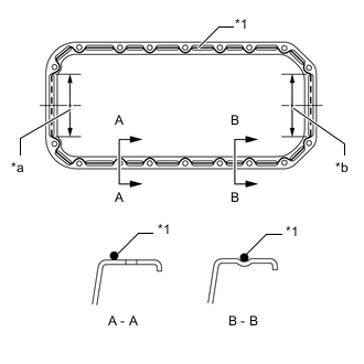
*1 Seal Packing *a Timing Belt Case Contact Portion *b Rear Oil Seal Retainer Contact Portion Apply seal packing to the oil pan sub-assembly as shown in the illustration.
Seal packing Toyota Genuine Seal Packing Black, Three Bond 1207B or equivalent Item Seal Packing Diameter Seal Packing Application Length Dashed line 7.0 mm (0.276 in.) 128 mm (5.04 in.) Continuous line 5.0 mm (0.197 in.) - Tech Tips
-
Do not apply an excessive amount to the surface, especially near the oil passages.
-
Parts must be assembled within 5 minutes of application. Otherwise the material must be removed and reapplied.
-
-
Install the oil pan sub-assembly with the 16 bolts and 2 nuts. Uniformly tighten the bolts and nuts in several steps.
- Torque:
- 18 N*m { 184 kgf*cm, 13 ft.*lbf }
-
-
INSTALL CRANKSHAFT TIMING PULLEY
-
INSTALL NO. 2 TIMING BELT IDLER SUB-ASSEMBLY
-
INSTALL NO. 1 TIMING BELT IDLER SUB-ASSEMBLY
-
INSTALL WATER PUMP ASSEMBLY
-
INSTALL NO. 2 TIMING BELT COVER
-
INSTALL CAMSHAFT TIMING PULLEY
-
INSTALL NO. 1 FRONT ENGINE MOUNTING BRACKET RH
-
INSTALL PUMP BRACKET
-
INSTALL WATER HOSE JOINT
-
INSTALL WATER OUTLET HOUSING
-
INSTALL NO. 1 COMPRESSOR MOUNTING BRACKET
-
INSTALL INJECTION PUMP ASSEMBLY
-
INSTALL TIMING BELT
-
INSTALL ENGINE ASSEMBLY