РАДИАТОР УСТАНОВКА
PROCEDURE
-
INSTALL RADIATOR DRAIN COCK PLUG
-
Install a new O-ring to the radiator drain cock plug.
-
Install the radiator drain cock plug to the radiator assembly.
-
-
INSTALL RADIATOR ASSEMBLY
-
Temporarily install the radiator assembly to the vehicle.
-
Attach the 2 guides and 2 claws to connect the cooler condenser assembly to the radiator assembly.
Note
-
Do not apply any excessive force to the cooler condenser assembly and cooler pipe.
-
Do not allow the radiator assembly to interfere with other parts.
-
-
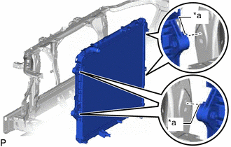
*a Claw Hook the claw of the radiator assembly as shown in the illustration.
-
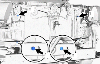
Install the radiator assembly with the 4 bolts in the order shown in the illustration.
- Torque:
- 22 N*m { 224 kgf*cm, 16 ft.*lbf }
-
-
CONNECT NO. 2 RADIATOR HOSE
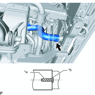
*a Paint Mark *b Protrusion
-
Connect the No. 2 radiator hose to the radiator assembly and slide the hose clamp to secure the hose.
Note
Connect the No. 2 radiator hose so that the paint mark on the No. 2 radiator hose is aligned with the protrusions of the radiator assembly as shown in the illustration.
-
-
INSTALL FAN SHROUD
-
Install the fan pulley to the engine water pump assembly.
-
Place the fan shroud together with the fluid coupling assembly between the engine and radiator assembly.
Note
Do not allow the radiator assembly to interfere with other parts.
-
Temporarily install the fluid coupling assembly to the engine water pump assembly with the 4 nuts.
Note
-
Make sure to match the paint mark colors on the fan with fluid coupling assembly with the stud bolts of the same color on the engine water pump assembly.
-
When installing the fan and generator V belt, make sure to securely tighten the nuts of the fan with fluid coupling assembly so that the fan pulley is properly aligned.
-
-
Attach the 2 guides and 2 claws to install the fan shroud to the radiator assembly.
-
Install the fan and generator V belt.
-
Tighten the 4 nuts holding the fan with fluid coupling assembly.
- Torque:
- 18 N*m { 184 kgf*cm, 13 ft.*lbf }
-
Attach the 2 wire harness clamps.
-
-
CONNECT NO. 1 OIL COOLER INLET HOSE (for Automatic Transmission)
-
Connect the No. 1 oil cooler inlet hose to the radiator assembly and slide the hose clamp to secure the hose.
-
Attach the clamp to connect the No. 1 oil cooler inlet hose to the fan shroud.
-
-
CONNECT NO. 1 OIL COOLER OUTLET HOSE (for Automatic Transmission)
-
Connect the No. 1 oil cooler outlet tube to the radiator assembly and slide the hose clamp to secure the hose.
-
-
INSTALL RADIATOR RESERVOIR
-
Install the radiator reservoir with the 2 bolts.
- Torque:
- 5.0 N*m { 51 kgf*cm, 44 in.*lbf }
-
Connect the water by-pass hose to the radiator assembly and slide the hose clamp to secure the hose.
-
Connect the No. 2 water by-pass hose to the radiator assembly and slide the hose clamp to secure the hose.
-
Attach the clamp to connect the No. 2 water by-pass hose to the fan shroud.
-
-
INSTALL OIL RESERVOIR BRACKET
-
Temporarily install the oil reservoir bracket with the 3 bolts and tighten the 3 bolts.
- Torque:
- 4.5 N*m { 46 kgf*cm, 40 in.*lbf }
-
-
CONNECT VANE PUMP OIL RESERVOIR ASSEMBLY
-
Attach the claw to connect the vane pump oil reservoir assembly to the oil reservoir bracket.
-
Attach the clamp to connect the pressure feed tube assembly to the fan shroud.
-
-
INSTALL NO. 1 RADIATOR HOSE
-
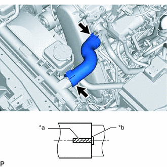
*a Paint Mark *b Protrusion Install the No. 1 radiator hose and slide the 2 hose clamps to secure the hose.
Note
Connect the No. 1 radiator hose so that the paint mark on the No. 1 radiator hose is aligned with the protrusions of the radiator assembly and water outlet as shown in the illustration.
-
-
ADD ENGINE COOLANT
-
INSPECT FOR COOLANT LEAK
-
INSTALL NO. 1 RADIATOR AIR GUIDE
-
Install the No. 1 radiator air guide with 4 new clips.
-
-
INSTALL NO. 1 ENGINE UNDER COVER ASSEMBLY
-
INSTALL RADIATOR SIDE DEFLECTOR
-
for Steel Type Bumper:
-
for Resin Type Bumper:
-
-
INSTALL NO. 1 ENGINE COVER SUB-ASSEMBLY