ВПУСКНОЙ КОЛЛЕКТОР СНЯТИЕ
CAUTION / NOTICE / HINT
Note
-
When replacing the parts in the following chart (A), replace the No. 1 injection pipe sub-assembly, No. 2 injection pipe sub-assembly, No. 3 injection pipe sub-assembly, No. 4 injection pipe sub-assembly and/or fuel inlet pipe sub-assembly with new ones.
Replaced Parts (A) Pipes Requiring New Replacement
-
Injector assembly (including shuffling the injector assemblies between the cylinders)
-
Common rail assembly
-
Cylinder head sub-assembly
-
No. 1 injection pipe sub-assembly
-
No. 2 injection pipe sub-assembly
-
No. 3 injection pipe sub-assembly
-
No. 4 injection pipe sub-assembly
-
Supply pump assembly
-
Common rail assembly
-
Cylinder block sub-assembly
-
Cylinder head sub-assembly
-
Cylinder head gasket
-
Timing Gear Case Assembly
Fuel inlet pipe sub-assembly -
-
After removing the No. 1 injection pipe sub-assembly, No. 2 injection pipe sub-assembly, No. 3 injection pipe sub-assembly, No. 4 injection pipe sub-assembly and fuel inlet pipe sub-assembly, clean them with a brush and compressed air.
PROCEDURE
-
PRECAUTION
Note
After turning the ignition switch off, waiting time may be required before disconnecting the cable from the battery terminal. Therefore, make sure to read the disconnecting the cable from the battery terminal notice before proceeding with work.
-
DISCONNECT CABLE FROM NEGATIVE BATTERY TERMINAL
Note
When disconnecting the cable, some systems need to be initialized after the cable is reconnected.
-
REMOVE DIESEL THROTTLE BODY ASSEMBLY
-
REMOVE MANIFOLD STAY
-
Remove the 2 bolts and manifold stay from the cylinder head sub-assembly and cylinder block sub-assembly.
-
-
REMOVE ENGINE OIL LEVEL DIPSTICK GUIDE
-
Remove the engine oil level dipstick.
-
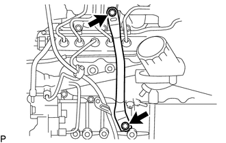
Remove the bolt and injection pipe clamp.
-
Remove the bolt and engine oil level dipstick guide.
-
Remove the O-ring from the engine oil level dipstick guide.
-
-
REMOVE VACUUM SWITCHING VALVE BRACKET
-
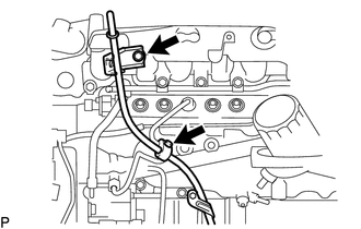
Remove the 2 bolts and vacuum switching valve bracket.
-
-
REMOVE NO. 2 INTAKE AIR CONNECTOR BRACKET
-
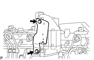
Remove the 3 bolts and No. 2 intake air connector bracket from the cylinder head sub-assembly and intake manifold.
-
-
REMOVE INTAKE AIR CONNECTOR
-
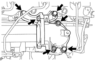
Remove the 2 nuts, bolt and intake air connector from the intake manifold.
-
-
REMOVE NO. 1, NO. 2 AND NO. 3 INJECTION PIPE SUB-ASSEMBLY
-
REMOVE NO. 4 INJECTION PIPE SUB-ASSEMBLY
-
REMOVE NO. 2 NOZZLE LEAKAGE PIPE ASSEMBLY
-
REMOVE INTAKE MANIFOLD
-
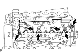
Remove the 4 bolts, 2 nuts, intake manifold and gasket.
-