КЛАПАН ПЕРЕКЛЮЧЕНИЯ ПОДАЧИ ВОЗДУХА (для моделей с вспомогательной системой подачи воздуха в нейтрализатор) СНЯТИЕ
CAUTION / NOTICE / HINT
CAUTION:
-
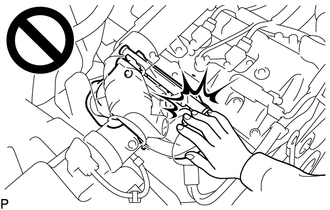
To prevent burns, do not touch the engine, exhaust manifold or other high temperature components while the engine is hot.
-
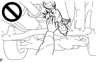
To prevent burns, do not touch the engine, exhaust pipe or other high temperature components while the engine is hot.
PROCEDURE
-
REMOVE FRONT FENDER SEAL RH
-
REMOVE AIR CLEANER CAP SUB-ASSEMBLY WITH NO. 1 AIR CLEANER HOSE
-
REMOVE AIR CLEANER FILTER ELEMENT SUB-ASSEMBLY
-
REMOVE AIR CLEANER CASE SUB-ASSEMBLY
-
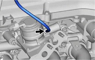
DISCONNECT NO. 4 AIR INJECTION SYSTEM HOSE
-
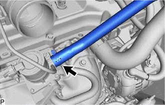
Slide the clip and disconnect the No. 4 air injection system hose from the air switching valve assembly.
-
-
REMOVE NO. 1 EXHAUST MANIFOLD HEAT INSULATOR
CAUTION:
To prevent burns, do not touch the engine, exhaust manifold or other high temperature components while the engine is hot.
-
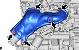
Remove the 5 bolts and No. 1 exhaust manifold heat insulator.
Tech Tips
-
It is only necessary to move the No. 1 exhaust manifold heat insulator so that the No. 4 intake pipe can be removed in a later step.
-
It is not possible to fully remove the No. 1 exhaust manifold heat insulator in this step.
-
-
-
REMOVE NO. 4 INTAKE PIPE
-
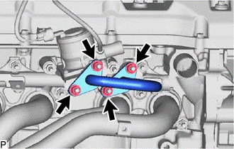
Remove the 4 nuts, No. 4 intake pipe and 2 gaskets.
Note
Be careful not to damage the installation surface of the gaskets.
-
-
REMOVE AIR SWITCHING VALVE ASSEMBLY
-
Disconnect the vacuum hose.
-
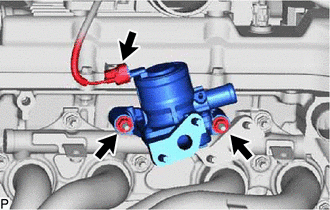
Disconnect the air switching valve connector.
-
Remove the 2 nuts and air switching valve assembly.
-
Remove the No. 1 exhaust manifold heat insulator.
-