ТОПЛИВНЫЙ БАК (для моделей с длинной колесной базой) СНЯТИЕ

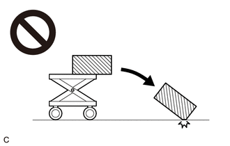
CAUTION / NOTICE / HINT
CAUTION:
The fuel tank assembly is very heavy. Be sure to follow the procedure described in the repair manual, or the fuel tank assembly may fall off the engine lifter.
PROCEDURE
-
PRECAUTION
Note
After turning the ignition switch off, waiting time may be required before disconnecting the cable from the battery terminal. Therefore, make sure to read the disconnecting the cable from the battery terminal notice before proceeding with work.
-
DISCONNECT CABLE FROM NEGATIVE BATTERY TERMINAL
Note
When disconnecting the cable, some systems need to be initialized after the cable is reconnected.
-
REMOVE FUEL TANK CAP ASSEMBLY
-
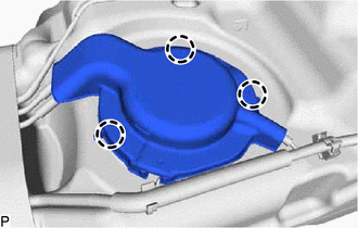
REMOVE NO. 1 FUEL TANK PROTECTOR
-
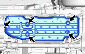
Remove the 5 nuts and No. 1 fuel tank protector from fuel tank bands.
-
-
DISCONNECT FUEL TANK MAIN TUBE SUB-ASSEMBLY AND FUEL TANK RETURN TUBE
-
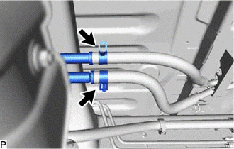
Slide the 2 clamps and disconnect the 2 fuel hoses from the fuel tank main tube sub-assembly and fuel tank return tube.
-
-
DISCONNECT FUEL TANK BREATHER HOSE
-
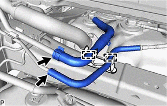
for Type A:
-
Detach the 2 clamps.
-
Slide the clamp and disconnect the fuel hose and fuel tank breater hose from the fuel tank filler pipe sub-assembly.
-
-
for Type B:
-
Detach the clamp.
-
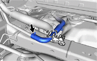
Slide the clamp and disconnect the fuel tank breater hose from the fuel tank filler pipe sub-assembly.
-
-
-
DISCONNECT FUEL TANK TO FILLER PIPE HOSE
-
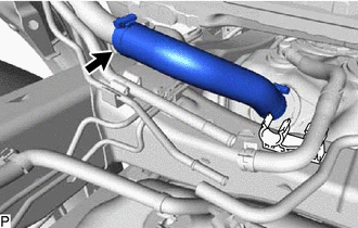
Loosen the clamp and disconnect the fuel tank to filler pipe hose from the fuel tank filler pipe sub-assembly.
-
-
REMOVE FUEL TANK ASSEMBLY
CAUTION:
The fuel tank assembly is very heavy. Be sure to follow the procedure described in the repair manual, or the fuel tank assembly may fall off the engine lifter.
-
Using an engine lifter and attachments, support the fuel tank assembly.
-
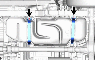
Remove the 2 bolts and disconnect the 2 fuel tank bands.
-
Remove the 2 clips, 2 fuel tank band pins and 2 fuel tank bands.
Tech Tips
Move the fuel tank assembly just enough to remove the fuel tank band pins.
-
Slightly lower the engine lifter.
Note
Be careful not to cut the wire harness.
-
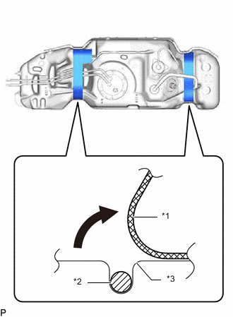
*1 Fuel Tank Cushion *2 Wire Harness *3 Fuel Tank Assembly Fold back approximately half of each fuel tank cushion so that the wire harness can be removed in the step below.
-
for Smart Cab:
Detach the 3 claws and remove the fuel tank protector.
-
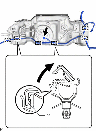
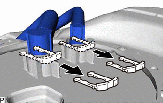
*a Claw Detach the wire harness from the 6 clamps shown in the illustration.
-
Disconnect the fuel sender gauge connector from the fuel tank vent tube assembly.
-
-
REMOVE NO. 1 FUEL TANK HEAT INSULATOR
-

Fuel Tank Bolt 
Nut Remove the nut.
-
Using needle-nose pliers, remove the 4 fuel tank bolts shown in the illustration, and then remove the No. 1 fuel tank heat insulator.
-
-
REMOVE FUEL TANK CUSHION
-
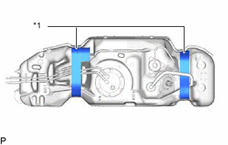
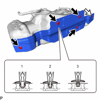
*1 Fuel Tank Cushion Remove the 2 fuel tank cushions from the fuel tank sub-assembly.
-
-
REMOVE NO. 3 FUEL TUBE CLAMP
-
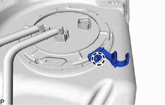
Detach the claw and remove the No. 3 fuel tube clamp.
-
-
REMOVE FUEL TANK VENT TUBE ASSEMBLY
-
Remove the 2 tube joint clips and pull out the fuel tank main tube sub-assembly and fuel tank return tube from the fuel tank vent tube assembly.
Note
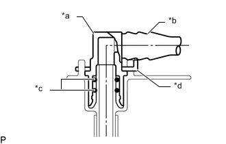
*a Fuel Tube Joint *b Fuel Tube *c O-Ring *d Tube Joint Clip
-
Remove any dirt and foreign matter on the fuel tube joint before performing this work.
-
Do not allow any scratches or foreign matter on the parts when disconnecting them, as the fuel tube joint contains the O-rings that seal the plug.
-
Perform this work by hand. Do not use any tools.
-
Do not forcibly bend or twist the nylon tube.
-
Protect the disconnected parts by covering them with plastic bags and tape after disconnecting the fuel tank main tube sub-assembly and fuel tank return tube.
-
-
Remove the fuel pump gauge retainer from the fuel tank assembly.
-
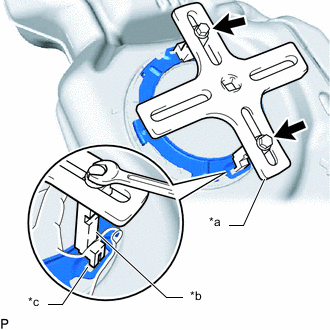
*a SST (Plate) *b SST (Claw) *c Insertion point SST (Bolt) Set the 2 claws and plate of SST on the fuel pump gauge retainer.
- SST
- 09808-14031 ( 09808-01010, 09808-01020, 09808-01030 )
- 09808-01071
Tech Tips
Securely insert the ends of SST into the insertion points in the fuel pump gauge retainer.
-
While firmly pressing the claws of SST into the insertion points in the fuel pump gauge retainer, tighten the bolts of the claws.
-
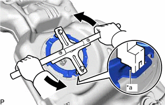
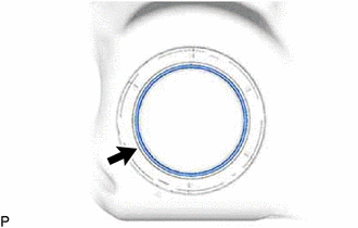
*a Insertion point Attach the handle of SST.
-
Check once more that the tip of SST is securely inserted into the insertion area of the fuel pump gauge retainer as shown in the illustration.
-
While lightly pressing down on SST so it does not come off the fuel pump gauge retainer, slowly turn the handle and remove the fuel pump gauge retainer.
Note
-
Do not use any tools other than SST, such as a screwdriver, etc.
-
Do not use excessive force when pressing down on SST, as the fuel pump gauge retainer will place excessive force on the fuel tank vent tube assembly and fuel pump gauge retainer and be difficult to remove, and parts may be damaged.
-
Be sure to keep the handle level when turning it, as SST may slip off the fuel pump gauge retainer if the handle is turned at an angle with excessive force.
-
Do not use an impact wrench or turn the handle with excessive force, as parts may be damaged.
-
If SST slips off the fuel pump gauge retainer, loosen the bolts and reattach SST to the fuel pump gauge retainer.
-
-
-
Remove the fuel tank vent tube assembly from the fuel tank sub-assembly.
Note
Be careful not to bend the arm of the fuel sender gauge assembly.
-
Remove the fuel tank vent tube gasket from the fuel tank sub-assembly.
-
-
REMOVE FUEL TANK TO FILLER PIPE HOSE
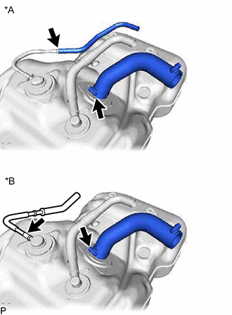
*A for Type A *B for Type B
-
for Type A:
-
Loosen the clamp and remove the fuel tank to filler pipe hose from the fuel tank sub-assembly.
-
Remove the fuel hose from the fuel tank evaporation tube sub-assembly.
-
-
for Type B:
-
Loosen the clamp and remove the fuel tank to filler pipe hose from the fuel tank sub-assembly.
-
Remove the No. 3 fuel tube joint from the fuel tank cut off valve.
-
-