НАГНЕТАЮЩИЙ ТОПЛИВНЫЙ НАСОС СНЯТИЕ

CAUTION / NOTICE / HINT
The necessary procedures (adjustment, calibration, initialization, or registration) that must be performed after parts are removed, installed, or replaced during the fuel supply pump assembly removal/installation are shown below.
| Replacement Part or Procedure | Necessary Procedures | Effects/Inoperative when not Performed | Link |
|---|---|---|---|
| Fuel supply pump assembly | Supply Pump Initialization | Engine startability | |
| Timing belt | Mode reset operation |
|
CAUTION:
-
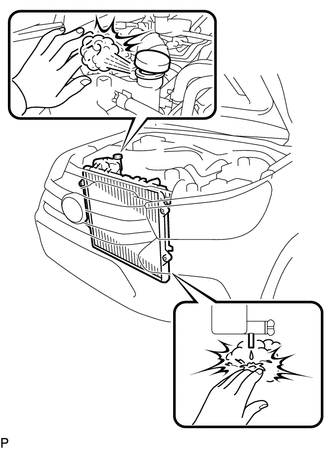
Do not remove the radiator reservoir cap sub-assembly, vent plug, radiator drain cock plug while the engine and radiator assembly are still hot. Pressurized, hot engine coolant and steam may be released and cause serious burns.
-
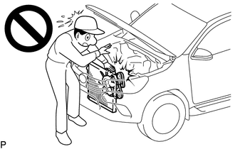
To prevent injury due to contact with an operating fan and generator V-belt or cooling fan, keep your hands and clothing away from the fan and generator V-belt and cooling fans when working in the engine compartment with the engine running.
-
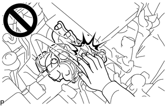
To prevent burns, do not touch the engine, exhaust manifold or other high temperature components while the engine is hot.
Note
-
When replacing the parts in the following chart (A), replace the No. 1 injection pipe sub-assembly, No. 2 injection pipe sub-assembly, No. 3 injection pipe sub-assembly, No. 4 injection pipe sub-assembly and/or fuel inlet pipe sub-assembly with new ones.
-
After removing the No. 1 injection pipe sub-assembly, No. 2 injection pipe sub-assembly, No. 3 injection pipe sub-assembly, No. 4 injection pipe sub-assembly and fuel inlet pipe sub-assembly, clean them with a brush and compressed air.
Replaced Parts (A) Pipes Requiring New Replacement
-
Injector assembly (including shuffling the injector assemblies between the cylinders)
-
Common rail assembly
-
Cylinder head sub-assembly
-
No. 1 injection pipe sub-assembly
-
No. 2 injection pipe sub-assembly
-
No. 3 injection pipe sub-assembly
-
No. 4 injection pipe sub-assembly
-
Supply pump assembly
-
Common rail assembly
-
Cylinder block sub-assembly
-
Cylinder head sub-assembly
-
Cylinder head gasket
-
Timing Gear Case Assembly
Fuel inlet pipe sub-assembly -
PROCEDURE
-
PRECAUTION
Note
After turning the ignition switch off, waiting time may be required before disconnecting the cable from the battery terminal. Therefore, make sure to read the disconnecting the cable from the battery terminal notice before proceeding with work.
-
DISCONNECT CABLE FROM NEGATIVE BATTERY TERMINAL
Note
When disconnecting the cable, some systems need to be initialized after the cable is reconnected.
-
REMOVE RADIATOR ASSEMBLY
-
REMOVE TIMING BELT
-
REMOVE ENGINE OIL LEVEL DIPSTICK GUIDE
-
REMOVE FUEL INLET PIPE SUB-ASSEMBLY
-
Using a 17 mm union nut wrench, loosen the union nuts and remove the fuel inlet pipe sub-assembly from the common rail assembly and fuel supply pump assembly.
-
-
REMOVE FUEL SUPPLY PUMP ASSEMBLY
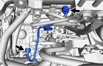
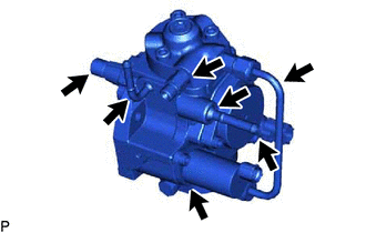
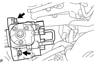
Note
Do not hold the supply pump assembly by the parts indicated by the arrows in the illustration.
-
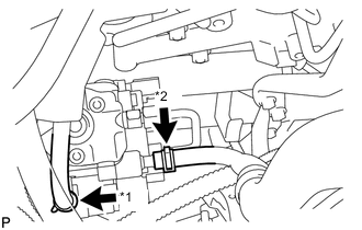
*1 Fuel Hose *2 No. 1 Fuel Hose Slide the 2 clamps and disconnect the fuel hose and No. 1 fuel hose from the fuel supply pump assembly.
-
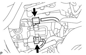
Disconnect the connector from the fuel temperature sensor.
-
Disconnect the connector from the suction control valve.
-
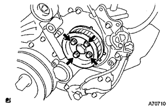
Remove the 4 bolts indicated by the arrows in the illustration.
-
Remove the No. 2 camshaft timing pulley flange and pump drive shaft pulley from the injection gear.
-
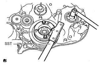
Remove the set nut and O-ring while holding the crankshaft pulley using SST.
- SST
- 09213-58014 ( 91551-80840 )
- 09330-00021
-
Loosen the 2 nuts.
-
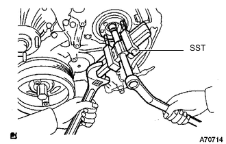
Using SST, disconnect the fuel supply pump assembly from the injection gear.
- SST
- 09950-50013 ( 09951-05010, 09952-05010, 09953-05020, 09954-05021 )
Note
Apply lubricant to the threads and tip of SST (center bolt) before using it.
-
Remove the 2 nuts and fuel supply pump assembly from the timing gear case assembly.
Note
-
Do not hold or carry the fuel supply pump assembly by the pipe.
-
The fuel supply pump assembly must be kept horizontal.
-
-
Remove the O-ring from the fuel supply pump assembly.
-