ДВИГАТЕЛЬ ПРОВЕРКА БЕЗ СНЯТИЯ С АВТОМОБИЛЯ

CAUTION / NOTICE / HINT
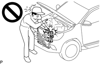
CAUTION:
To prevent injury due to contact with an operating fan and generator V-belt or cooling fan, keep your hands and clothing away from the fan and generator V-belt and cooling fans when working in the engine compartment with the engine running.
Tech Tips
The type of ignition switch used on this model differs according to the specifications of the vehicle. For the expressions listed in this section, refer to the "Ignition Switch Expressions" precaution.
PROCEDURE
-
INSPECT ENGINE COOLANT
-
INSPECT ENGINE OIL
-
INSPECT BATTERY
-
INSPECT AIR CLEANER FILTER ELEMENT SUB-ASSEMBLY
-
Remove the air cleaner filter element sub-assembly from the air cleaner case.
-
Check that the air cleaner filter element sub-assembly is not excessively dirty.
If the air cleaner filter element sub-assembly is excessively dirty, replace the air cleaner filter element sub-assembly.
If cleaning the air cleaner filter element sub-assembly, blow compressed air to clean it.
Note
-
Do not start the engine with the air cleaner filter element sub-assembly removed, as this may damage the engine.
-
When using an air cleaner filter element sub-assembly that uses compressed air, wear safety glasses and a dust mask in order to protect your health.
Tech Tips
When an excessive amount of dirt is present, replace the air cleaner filter element sub-assembly.
-
-
Reinstall the air cleaner filter element sub-assembly to the air cleaner case.
-
-
INSPECT SPARK PLUG
-
INSPECT FAN AND GENERATOR V BELT
-
INSPECT V-RIBBED BELT TENSIONER ASSEMBLY
-
INSPECT NO. 1 IDLER PULLEY
-
Idle the engine, and then stop the engine. Check that the fan and generator V belt is between the edges of the idler pulley.
-
Remove the fan and generator V belt.
-
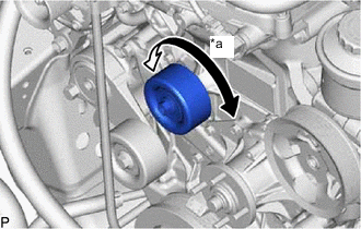
*a Turn Turn the pulley, and check that the idler bearing moves smoothly and quietly.
If necessary, replace the No. 1 idler pulley.
-
Install the fan and generator V belt.
-
-
INSPECT VALVE LASH ADJUSTER NOISE
-
Rev up the engine several times. Check that the engine does not emit unusual noises.
-
If unusual noises occur, warm up the engine and idle it for 30 minutes or more, then perform the preceding inspection.
Tech Tips
If any defects or problems are found during the preceding inspection, perform valve lash adjuster assembly inspection.
-
-
INSPECT IGNITION TIMING
-
Warm up and stop the engine.
-
When using the GTS:
-
Connect the GTS to the DLC3.
Note
Switch off all the accessories and the A/C before connecting the GTS.
-
Start the engine and idle it.
-
Turn the GTS on.
-
Enter the following menus: Powertrain / Engine / Data List / IGN Advance.
Powertrain > Engine > Data ListTester Display IGN Advance Standard ignition timing 2 to 15° BTDC @ idle Note
When checking the ignition timing, the transmission should be in N or P.
Tech Tips
Refer to the GTS operator's manual for further details.
-
Check that the ignition timing advances immediately when the engine speed is increased.
-
Enter the following menus: Powertrain / Engine / Active Test / Connect the TC and TE1.
Powertrain > Engine > Active TestTester Display Connect the TC and TE1 -
Monitor IGN Advance.
-
Perform the Active Test.
Standard ignition timing 3 to 7° BTDC @ idle Note
When checking the ignition timing, the transmission should be in N or P.
Tech Tips
Refer to the GTS operator's manual for further details.
-
-
When not using the GTS:
-
Connect the tester probe of a timing light to the wire of the ignition coil connector for the No. 1 cylinder.
Note
Use a timing light that detects primary signals.
-
Start the engine and idle it.
-
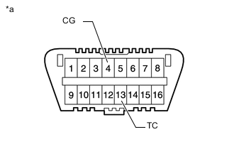
*a Front view of DLC3 Using SST, connect terminals 13 (TC) and 4 (CG) of the DLC3.
- SST
- 09843-18040
Note
When checking the ignition timing, the transmission should be in N or P.
-
Using the timing light, measure the ignition timing.
Standard ignition timing 3 to 7° BTDC @ idle Note
-
Turn all the electrical systems and the A/C off.
-
When checking the ignition timing, the transmission should be in N or P.
-
-
Remove SST from the DLC3.
-
Check the ignition timing.
Standard ignition timing 2 to 15° BTDC @ idle -
Confirm that the ignition timing advances immediately when the engine speed is increased.
-
Turn the ignition switch off.
-
Disconnect the timing light from the wire of the ignition coil connector for the No. 1 cylinder.
-
-
-
INSPECT ENGINE IDLE SPEED
-
Warm up and stop the engine.
-
When using the GTS:
-
Connect the GTS to the DLC3.
Note
Switch off all accessories and the A/C before connecting the GTS.
-
Start the engine and idle it.
-
Turn the GTS on.
-
Enter the following menus: Powertrain / Engine / Data List / Engine Speed.
Powertrain > Engine > Data ListTester Display Engine Speed Standard idle speed 600 to 700 rpm Note
When checking the idle speed, the transmission should be in N or P.
Tech Tips
Refer to the GTS operator's manual for further details.
-
Turn the ignition switch off.
-
Disconnect the GTS from the DLC3.
-
-
When not using the GTS:
-
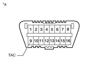
*a Front view of DLC3 Using SST, connect a tachometer tester probe to terminal 9 (TAC) of the DLC3.
- SST
- 09843-18030
Note
Switch off all accessories and the A/C before connecting the terminals.
-
Start the engine and idle it.
-
Check the idle speed.
Standard idle speed 600 to 700 rpm
-
-
-
INSPECT COMPRESSION
-
Warm up and stop the engine.
-
Check for DTCs.
Powertrain > Engine > Trouble Codes -
Disconnect the 4 fuel injector connectors.
-
Remove the 4 spark plugs.
-
Check the cylinder compression pressure.
-
Insert a compression gauge into the spark plug hole.
-
Fully open the throttle.
-
While cranking the engine, measure the compression pressure.
Standard compression pressure 1230 kPa (12.5 kgf/cm2, 178 psi) or higher Minimum pressure 880 kPa (9.0 kgf/cm2, 128 psi) Difference between each cylinder 68 kPa (0.7 kgf/cm2, 9.9 psi) or less Note
-
Use a fully-charged battery so the engine speed can be increased to 250 rpm or more.
-
Inspect the other cylinders in the same way.
-
Measure the compression in as short a time as possible.
-
-
If the cylinder compression pressure is low, pour a small amount of engine oil into the cylinder through the spark plug hole and inspect it again.
Tech Tips
-
If adding oil increases the compression pressure, the piston rings and/or cylinder bore may be worn or damaged.
-
If the compression pressure stays low, the valve may be stuck or seated improperly, or there may be leakage from the gasket.
-
-
-
Install the 4 spark plugs.
-
Connect the 4 fuel injector connectors.
-
Check for DTCs.
Powertrain > Engine > Trouble Codes
-
-
CHECK CO/HC
-
Start and warm up the engine.
-
Run the engine at 2500 rpm for approximately 180 seconds, and then idle the engine.
-
Insert a CO/HC meter testing probe at least 40 cm (1.31 ft.) into the tail exhaust pipe assembly.
-
Check the CO/HC concentration at idle.
Standard idle CO concentration 0 to 0.5% Standard idle HC concentration Refer to applicable local regulation -
If the CO/HC concentration is not as specified, perform troubleshooting in the order given below.
-
Check the air fuel ratio sensor operation.
-
Check the heated oxygen sensor operation.
-
See the table below for possible causes, and then inspect and repair the applicable causes if necessary.
CO HC Problems Causes Normal High Rough idle
-
Faulty ignition:
-
Incorrect timing
-
Fouled, shorted or improperly gapped plugs
-
Incorrect valve clearance (valve lash adjuster assembly)
-
Leaks in intake and exhaust valves
-
Leaks in cylinders
Low High Rough idle
(Fluctuating HC reading)
-
Vacuum leaks:
-
PCV hoses
-
Intake manifold
-
Throttle body with motor assembly
-
Brake booster line
-
Lean mixture causing misfire
High High Rough idle
(Black smoke from exhaust)
-
Restricted air cleaner filter element sub-assembly
-
Plugged PCV valve sub-assembly
-
Faulty SFI system:
-
Faulty fuel pressure regulator assembly
-
Defective engine coolant temperature sensor
-
Defective intake mass air flow meter sub-assembly
-
Faulty ECM
-
Faulty fuel injector assemblies
-
Faulty throttle body with motor assembly
-
-
-