ПРОКЛАДКА ГОЛОВКИ БЛОКА ЦИЛИНДРОВ СНЯТИЕ
CAUTION / NOTICE / HINT
The necessary procedures (adjustment, calibration, initialization, or registration) that must be performed after parts are removed, installed, or replaced during the cylinder head gasket removal/installation are shown below.
| Replacement Part or Procedure | Necessary Procedures | Effects/Inoperative when not Performed | Link |
|---|---|---|---|
| Replacement of ECM | Vehicle Identification Number (VIN) registration | DTC P0630 is output | |
| Code registration (Immobiliser system) | Engine start function | See the Service Bulletin for the registration method. | |
| Replacement of engine assembly | Inspection after repair | Poor idle, engine start, etc. | |
|
Inspection after repair | Poor idle, engine start, etc. | |
for AC60E: |
Reset memory |
|
|
for AC60E: |
ATF thermal degradation estimate reset | The value of the Data List item "ATF Thermal Degradation Estimate" is not estimated correctly | |
for AC60E: |
Reset memory |
|
|
for AC60E: |
ATF thermal degradation estimate reset | The value of the Data List item "ATF Thermal Degradation Estimate" is not estimated correctly |
PROCEDURE
-
REMOVE TIMING CHAIN COVER SUB-ASSEMBLY
-
REMOVE EXHAUST MANIFOLD
-
SET NO. 1 CYLINDER TO TDC/COMPRESSION
-
REMOVE CYLINDER HEAD COVER CONNECTOR SUB-ASSEMBLY
-
REMOVE TIMING CHAIN GUIDE
-
REMOVE NO. 1 CHAIN TENSIONER ASSEMBLY
-
REMOVE CHAIN TENSIONER SLIPPER
-
REMOVE NO. 1 CHAIN VIBRATION DAMPER
-
REMOVE CHAIN SUB-ASSEMBLY
-
REMOVE CAMSHAFT BEARING CAP
-
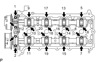
Uniformly loosen and remove the 20 bolts in the sequence shown in the illustration.
Note
Uniformly loosen the bolts while keeping the camshafts level.
-
Remove the No. 1 camshaft bearing cap and 4 No. 2 camshaft bearing caps.
Tech Tips
Arrange the removed parts in the correct order.
-
-
REMOVE CAMSHAFT
-
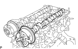
Remove the camshaft.
-
-
REMOVE NO. 2 CAMSHAFT
-
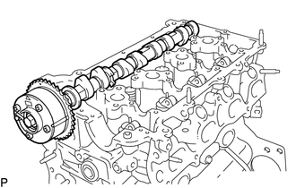
Remove the No. 2 camshaft.
-
-
REMOVE NO. 1 VALVE ROCKER ARM SUB-ASSEMBLY
-
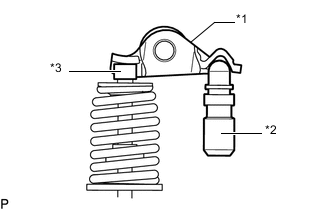
*1 No. 1 Valve Rocker Arm Sub-assembly *2 Valve Lash Adjuster Assembly *3 Valve Stem Cap Remove the 16 No. 1 valve rocker arm sub-assemblies from the cylinder head sub-assembly.
Tech Tips
Arrange the removed parts in the correct order.
-
-
REMOVE VALVE LASH ADJUSTER ASSEMBLY
-
Remove the 16 valve lash adjuster assemblies from the cylinder head sub-assembly.
Tech Tips
Arrange the removed parts in the correct order.
-
-
REMOVE VALVE STEM CAP
-
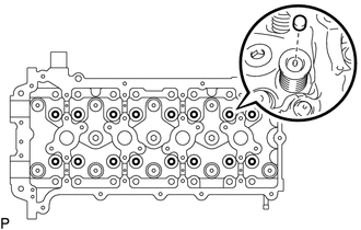
Remove the 16 valve stem caps from the cylinder head sub-assembly.
Tech Tips
Arrange the removed parts in the correct order.
-
-
DISCONNECT ENGINE WIRE
-
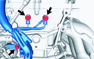
Remove the 3 bolts and disconnect the engine wire from the cylinder head sub-assembly.
-
-
REMOVE CYLINDER HEAD SUB-ASSEMBLY
-
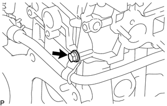
w/ Oil Cooler:
Remove the bolt and disconnect the No. 4 water by-pass pipe.
-
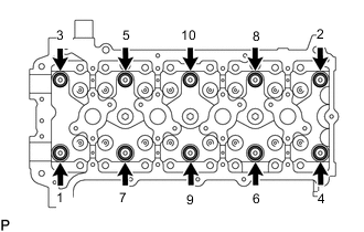
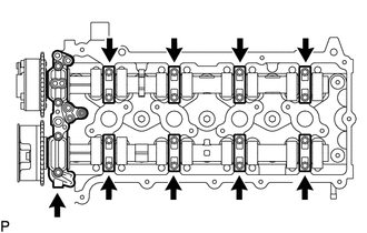
Uniformly loosen the 10 cylinder head set bolts in the sequence shown in the illustration. Remove the 10 cylinder head set bolts and plate washers.
Note
-
Be careful not to drop the washers into the cylinder head sub-assembly.
-
Head warpage or cracking could result from removing the cylinder head set bolts in the wrong order.
-
-
Remove the cylinder head sub-assembly.
-
-
REMOVE CYLINDER HEAD GASKET
-
Remove the cylinder head gasket from the cylinder block sub-assembly.
-
-
INSPECT CYLINDER HEAD SET BOLT
-
INSPECT CYLINDER HEAD SUB-ASSEMBLY