РАСПРЕДВАЛ СНЯТИЕ

CAUTION / NOTICE / HINT
The necessary procedures (adjustment, calibration, initialization or registration) that must be performed after parts are removed, installed, or replaced during the camshaft removal/installation are shown below.
| Replacement Part or Procedure | Necessary Procedures | Effects/Inoperative when not Performed | Link |
|---|---|---|---|
|
Inspection after repair | Poor idle, engine start etc. |
CAUTION:
To prevent burns, do not touch the engine, exhaust manifold or other high temperature components while the engine is hot.
PROCEDURE
-
PRECAUTION
Note
After turning the ignition switch off, waiting time may be required before disconnecting the cable from the battery terminal. Therefore, make sure to read the disconnecting the cable from the battery terminal notice before proceeding with work.
-
DISCONNECT CABLE FROM NEGATIVE BATTERY TERMINAL
Note
When disconnecting the cable, some systems need to be initialized after the cable is reconnected.
-
REMOVE FAN AND GENERATOR V BELT
-
REMOVE INTAKE AIR CONNECTOR
-
REMOVE IGNITION COIL ASSEMBLY
-
REMOVE CYLINDER HEAD COVER SUB-ASSEMBLY
-
REMOVE CYLINDER HEAD COVER CONNECTOR SUB-ASSEMBLY
-
REMOVE TIMING CHAIN GUIDE
-
SET NO. 1 CYLINDER TO TDC/COMPRESSION
-
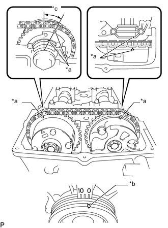
*a Timing Mark *b Groove *c Approximately 13° Turn the crankshaft pulley, and align its groove with the "0" timing mark of the timing chain cover sub-assembly.
-
Check that the timing marks of the camshaft timing gear assembly and camshaft timing exhaust gear assembly are aligned with the timing marks of the No. 1 camshaft bearing cap as shown in the illustration.
Tech Tips
If the timing marks do not align, rotate the crankshaft clockwise again and align the timing marks.
-
-
REMOVE NO. 1 CHAIN TENSIONER ASSEMBLY
-
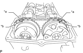
*a Paint Mark *b Timing Mark Place paint marks on the chain sub-assembly, camshaft timing gear assembly and camshaft timing exhaust gear assembly.
-
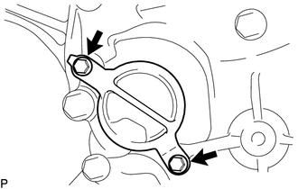
Remove the 2 bolts and timing chain cover plate from the timing chain cover sub-assembly.
-
Remove the gasket from the timing chain cover plate.
-
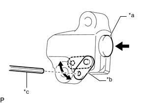
*a Plunger *b Stopper Plate *c Hexagon Wrench Move the stopper plate upward to release the lock and push the plunger deep into the No. 1 chain tensioner assembly.
-
Move the stopper plate downward to set the lock and insert a hexagon wrench into the stopper plate hole.
-
Remove the bolt, nut, No. 1 chain tensioner assembly and gasket.
-
-
REMOVE NO. 2 CAMSHAFT
-
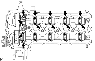
Uniformly loosen the 12 bolts and then remove the No. 1 camshaft bearing cap and 4 No. 2 camshaft bearing caps.
Note
Uniformly loosen the bolts while keeping the No. 2 camshaft level.
-
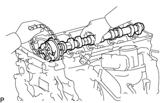
Move the camshaft in the direction shown in the illustration to loosen the chain sub-assembly, and then remove the No. 2 camshaft.
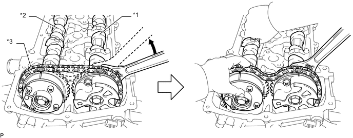
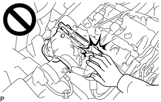
*1 Camshaft *2 No. 2 Camshaft *3 Chain Sub-assembly - - Note
Do not pry the No. 2 camshaft with a tool as an excessive amount of force may be applied to it.
-
-
REMOVE CAMSHAFT
-
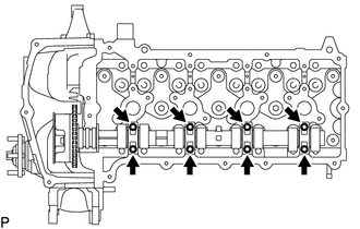
Uniformly loosen the 8 bolts and then remove the 4 No. 2 camshaft bearing caps.
Note
Uniformly loosen the bolts while keeping the camshaft level.
-
Remove the camshaft while holding the chain sub-assembly.
Note
Do not pry the camshaft with a tool as an excessive amount of force may be applied to it.
-
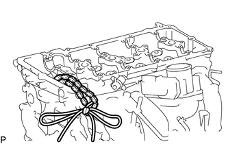
Secure the chain sub-assembly with a string as shown in the illustration.
Note
Be careful not to drop anything inside the timing chain cover sub-assembly.
-
-
INSPECT CAMSHAFT TIMING GEAR ASSEMBLY
-
Check the lock of the camshaft timing gear assembly.
-
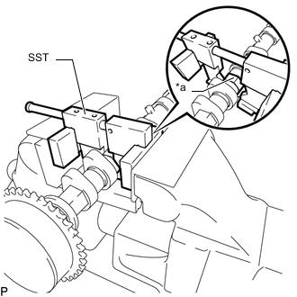
*a Hexagonal Portion Using SST, grip the hexagonal portion, and then secure SST and camshaft in a vise as shown in the illustration and check that the camshaft timing gear assembly does not rotate.
- SST
- 09212-31010
Note
-
Do not damage the camshaft.
-
Never grip areas other than the hexagonal portion, as this may cause damage.
-
-
Release the lock pin.
-
Clean the camshaft journal with non-residue solvent.
-
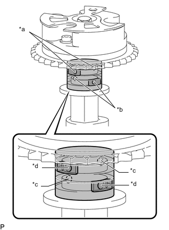
*a Retard Side Path *b Advance Side Path *c Open *d Close 
Rubber Piece 
Vinyl Tape Cover the 4 oil paths of the cam journal with vinyl tape as shown in the illustration.
Tech Tips
1 retard side path and 1 advance side path are provided in the groove of the camshaft. Plug one of the paths with a rubber piece.
-
Break through the tape over the advance side path, and then break through the tape over the retard side path on the opposite side from the hole over the advance side path as shown in the illustration.
-
*a Retard Side Path *b Advance Side Path Apply compressed air at approximately 200 kPa (2.0 kgf/cm2, 28 psi) to the 2 open paths accessible through the holes in the tape.
Note
Cover the paths with a piece of cloth when applying pressure to keep oil from splashing.
-
*a Retard Side Path *b Advance Side Path *c Decompress *d Hold Pressure Check that the camshaft timing gear assembly revolves in the advance direction when reducing the air pressure applied to the retard side path.
OK Gear rotates in the advance direction. Tech Tips
This operation releases the lock pin which holds the timing gear in the most retarded position.
-
When the camshaft timing gear assembly reaches the most advanced position, release the air pressure from the retard side path and advance side path in that order.
Note
-
Do not release the air pressure from the advance side path first. The gear may abruptly shift in the retard direction and break the lock pin.
-
When releasing the air pressure from the advance side path, release it slowly.
-
-
-
Check for smooth rotation.
-
Rotate the camshaft timing gear assembly within its movable range several times, but do not turn it to the most retarded position. Check that the gear rotates smoothly.
CAUTION:
Do not use air pressure to perform the smooth operation check.
-
-
Check the lock in the most retarded position.
-
Confirm that the camshaft timing gear assembly becomes locked at the most retarded position.
-
-
-
REMOVE CAMSHAFT TIMING GEAR ASSEMBLY
-
*a Hexagonal Portion Using SST, grip the hexagonal portion, and then secure SST and camshaft in a vise as shown in the illustration.
- SST
- 09212-31010
Note
-
Do not damage the camshaft.
-
Never grip areas other than the hexagonal portion, as this may cause damage.
-
*1 Flange Bolt *a Straight Pin *b Do Not Remove Remove the flange bolt and camshaft timing gear assembly.
Note
-
Be sure not to remove the other 3 bolts.
-
If planning to reuse the gear, be sure to release the straight pin lock before installing the gear.
-
-
-
INSPECT CAMSHAFT TIMING EXHAUST GEAR ASSEMBLY
-
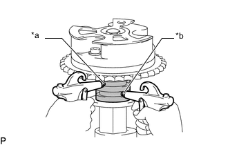
Check the lock of the camshaft timing exhaust gear assembly.
-
*a Hexagonal Portion Using SST, grip the hexagonal portion, and then secure SST and No. 2 camshaft in a vise as shown in the illustration and check that the camshaft timing exhaust gear assembly does not rotate.
- SST
- 09212-31010
Note
-
Do not damage the No. 2 camshaft.
-
Never grip areas other than the hexagonal portion, as this may cause damage.
-
-
Release the lock pin.
-
Clean the No. 2 camshaft journal with non-residue solvent.
-
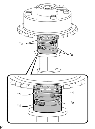
*a Retard Side Path *b Advance Side Path *c Open *d Close Rubber Piece Vinyl Tape Cover the 4 oil paths of the cam journal with vinyl tape as shown in the illustration.
Tech Tips
There are 4 oil paths in the grooves of the No. 2 camshaft. Plug 2 paths with pieces of rubber.
-
Break through the tape over the advance side path, and then break through the tape over the retard side path on the opposite side from the hole over the advance side path as shown in the illustration.
-
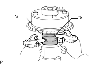
*a Retard Side Path *b Advance Side Path Apply compressed air at approximately 200 kPa (2.0 kgf/cm2, 28 psi) to the 2 open paths (the advance side path and retard side path).
Note
Cover the paths with a piece of cloth when applying pressure to keep oil from splashing.
Tech Tips
The lock pin is released in this condition.
-
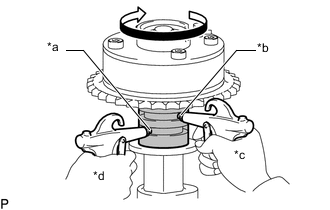
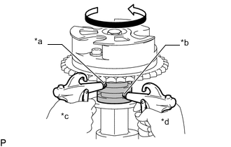
*a Retard Side Path *b Advance Side Path *c Decompress *d Hold Pressure Check that the camshaft timing exhaust gear assembly turns in the retard direction when reducing the air pressure applied to the advance side path.
Tech Tips
The lock pin is released and the camshaft timing exhaust gear assembly turns in the retard direction.
-
When the camshaft timing exhaust gear assembly moves to the most retarded position, release the air pressure from the advance side path, and then release the air pressure from the retard side path.
Note
Be sure to release the air pressure from the advance side path first. If the air pressure of the retard side path is released first, the camshaft timing exhaust gear assembly may abruptly shift in the advance direction and break the lock pin or other parts.
-
-
Check for smooth rotation.
-
Turn the camshaft timing exhaust gear assembly within its movable range (21.5 to 23.5°) 2 or 3 times, but do not turn it to the most advanced position. Make sure that the gear turns smoothly.
Note
When the air pressure is released from the advance side path and then from the retard side path, the gear automatically returns to the most advanced position due to the advance assist spring operation, and locks. Gradually release the air pressure from the retard side path before performing the smooth rotation check.
-
-
Check the lock at the most advanced position.
-
Make sure that the camshaft timing exhaust gear assembly locks at the most advanced position.
-
-
-
REMOVE CAMSHAFT TIMING EXHAUST GEAR ASSEMBLY
-
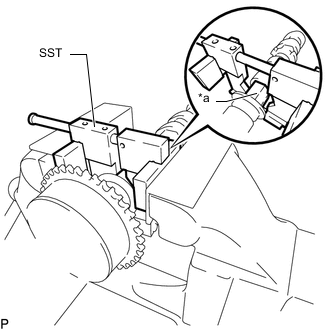
*a Hexagonal Portion Using SST, grip the hexagonal portion, and then secure SST and No. 2 camshaft in a vise as shown in the illustration.
- SST
- 09212-31010
Note
-
Do not damage the No. 2 camshaft.
-
Never grip areas other than the hexagonal portion, as this may cause damage.
-
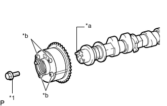
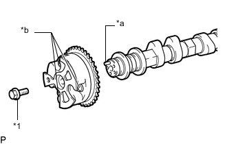
*1 Flange Bolt *a Straight Pin *b Do Not Remove Remove the flange bolt and camshaft timing exhaust gear assembly.
Note
Be sure not to remove the other 4 bolts.
-