БЛОК ДВИГАТЕЛЯ СНЯТИЕ

CAUTION / NOTICE / HINT
Note
-
When replacing the parts in the following chart (A), replace the No. 1 injection pipe sub-assembly, No. 2 injection pipe sub-assembly, No. 3 injection pipe sub-assembly, No. 4 injection pipe sub-assembly and/or fuel inlet pipe sub-assembly with new ones.
Replaced Parts (A) Pipes Requiring New Replacement
-
Injector assembly (including shuffling the injector assemblies between the cylinders)
-
Common rail assembly
-
Cylinder head sub-assembly
-
No. 1 injection pipe sub-assembly
-
No. 2 injection pipe sub-assembly
-
No. 3 injection pipe sub-assembly
-
No. 4 injection pipe sub-assembly
-
Supply pump assembly
-
Common rail assembly
-
Cylinder block sub-assembly
-
Cylinder head sub-assembly
-
Cylinder head gasket
-
Timing Gear Case Assembly
Fuel inlet pipe sub-assembly -
-
After removing the No. 1 injection pipe sub-assembly, No. 2 injection pipe sub-assembly, No. 3 injection pipe sub-assembly, No. 4 injection pipe sub-assembly and fuel inlet pipe sub-assembly, clean them with a brush and compressed air.
PROCEDURE
-
REMOVE NO. 1 TIMING BELT COVER
-
REMOVE TIMING BELT
-
REMOVE NO. 1 TIMING BELT IDLER SUB-ASSEMBLY
-
REMOVE CRANKSHAFT PULLEY SUB-ASSEMBLY
-
REMOVE VENTILATION HOSE HEAT INSULATOR
-
Remove the 2 bolts and ventilation hose heat insulator from the cylinder head sub-assembly.
-
-
REMOVE EXHAUST MANIFOLD WITH TURBOCHARGER
-
REMOVE NO. 2 IDLE PULLEY ASSEMBLY
-
REMOVE GENERATOR ASSEMBLY
-
REMOVE GENERATOR BRACKET
-
Remove the bolt and generator bracket.
-
-
REMOVE V-RIBBED BELT TENSIONER ASSEMBLY
-
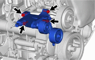
Remove the 4 bolts and V-ribbed belt tensioner assembly from the cylinder block sub-assembly.
-
-
REMOVE NO. 1 COMPRESSOR MOUNTING BRACKET
-
Remove the 4 bolts and No. 1 compressor mounting bracket from the cylinder block sub-assembly.
-
-
REMOVE WATER INLET
-
REMOVE THERMOSTAT
-
REMOVE WATER OUTLET
-
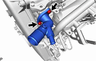
Remove the 2 bolts, water outlet and gasket from the cylinder head sub-assembly.
-
-
REMOVE DIESEL THROTTLE BODY ASSEMBLY
-
REMOVE INTAKE MANIFOLD
-
REMOVE NO. 2 EGR HOLE COVER PLATE
-
Remove the 2 nuts and No. 2 EGR hole cover plate.
-
Remove the gasket.
-
-
REMOVE GLOW PLUG ASSEMBLY
-
REMOVE COMMON RAIL ASSEMBLY
-
REMOVE INJECTION OR SUPPLY PUMP ASSEMBLY
-
REMOVE OIL COOLER COVER SUB-ASSEMBLY
-
REMOVE VACUUM PUMP ASSEMBLY
-
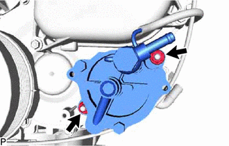
Remove the 2 nuts, vacuum pump assembly and 2 O-rings from the timing gear cover.
-
-
REMOVE VANE PUMP ASSEMBLY
-
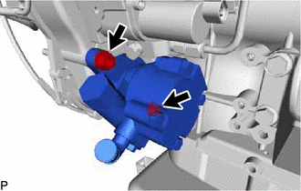
Remove the 2 nuts, vane pump assembly and O-ring from the timing gear case assembly.
-
-
REMOVE CRANKSHAFT POSITION SENSOR
-
REMOVE CAMSHAFT POSITION SENSOR
-
REMOVE ENGINE COOLANT TEMPERATURE SENSOR
-
REMOVE FRONT NO. 1 ENGINE MOUNTING BRACKET RH
-
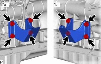
*a LH Side *b RH Side Remove the 4 bolts and front No. 1 engine mounting bracket RH from the cylinder block sub-assembly.
-
-
REMOVE FRONT NO. 1 ENGINE MOUNTING BRACKET LH
-
Remove the 4 bolts and front No. 1 engine mounting bracket LH from th cylinder block sub-assembly.
-