ПРИВОДНОЙ РЕМЕНЬ ГАЗОРАСПРЕДЕЛЕНИЯ СНЯТИЕ
CAUTION / NOTICE / HINT
The necessary procedures (adjustment, calibration, initialization, or registration) that must be performed after parts are removed, installed, or replaced during the camshaft sub-assembly removal/installation are shown below.
| Replacement Part or Procedure | Necessary Procedures | Effects/Inoperative when not Performed | Link |
|---|---|---|---|
| Replacement of injector assembly |
|
Engine starting | |
| Replacement of timing belt | Mode reset operation |
|
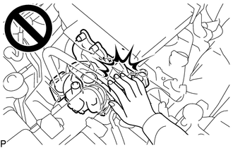
CAUTION:
To prevent burns, do not touch the engine, exhaust manifold or other high temperature components while the engine is hot.
Note
-
When replacing the parts in the following chart (A), replace the No. 1 injection pipe sub-assembly, No. 2 injection pipe sub-assembly, No. 3 injection pipe sub-assembly, No. 4 injection pipe sub-assembly and/or fuel inlet pipe sub-assembly with new ones.
Replaced Parts (A) Pipes Requiring New Replacement
-
Injector assembly (including shuffling the injector assemblies between the cylinders)
-
Common rail assembly
-
Cylinder head sub-assembly
-
No. 1 injection pipe sub-assembly
-
No. 2 injection pipe sub-assembly
-
No. 3 injection pipe sub-assembly
-
No. 4 injection pipe sub-assembly
-
Supply pump assembly
-
Common rail assembly
-
Cylinder block sub-assembly
-
Cylinder head sub-assembly
-
Cylinder head gasket
-
Timing Gear Case Assembly
Fuel inlet pipe sub-assembly -
-
After removing the No. 1 injection pipe sub-assembly, No. 2 injection pipe sub-assembly, No. 3 injection pipe sub-assembly, No. 4 injection pipe sub-assembly and fuel inlet pipe sub-assembly, clean them with a brush and compressed air.
PROCEDURE
-
REMOVE NO. 1 ENGINE UNDER COVER SUB-ASSEMBLY
-
DRAIN ENGINE COOLANT
-
REMOVE NO, 1 RADIATOR HOSE
-
REMOVE FAN SHROUD
-
REMOVE NO. 1 TIMING BELT COVER
-
Remove the 6 bolts, 6 washers and No. 1 timing belt cover from the No. 2 timing belt cover and timing gear cover.
-
-
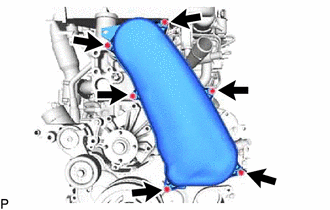
REMOVE TIMING BELT
-
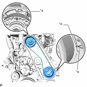
*a Timing Mark Turn the crankshaft clockwise and align the timing marks as shown in the illustration.
Tech Tips
If reusing the timing belt, place matchmarks on the timing belt so that it can be installed exactly as before.
-
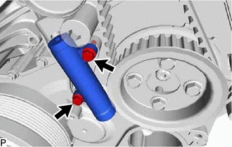
Uniformly loosen and remove the 2 bolts and No. 1 timing belt tensioner assembly from the timing gear cover.
-
Remove the timing belt.
Tech Tips
-
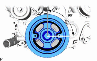
If turning the camshaft sub-assembly while the timing belt is removed, turn the crankshaft 90° counterclockwise as shown in the illustration.
-
When installing the timing belt, turn the camshaft sub-assembly to align the timing marks, and then turn the crankshaft clockwise to align the timing marks.
-
-
-
REMOVE NO. 1 TIMING BELT IDLER SUB-ASSEMBLY
Note
When inspecting the No. 1 timing belt idler sub-assembly, do not remove it unless absolutely necessary.
-
Using a 10 mm hexagon wrench, remove the timing belt idler shaft, No. 1 timing belt idler sub-assembly and timing belt idler spacer from the timing gear cover.
-