ДВИГАТЕЛЬ ПРОВЕРКА БЕЗ СНЯТИЯ С АВТОМОБИЛЯ

CAUTION / NOTICE / HINT
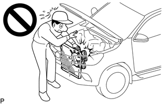
CAUTION:
To prevent injury due to contact with an operating fan and generator V belt or cooling fan, keep your hands and clothing away from the fan and generator V belt and cooling fans when working in the engine compartment with the engine running.
Tech Tips
The type of ignition switch used on this model differs according to the specifications of the vehicle. For the expressions listed in this section, refer to the "Ignition Switch Expressions" precaution.
PROCEDURE
-
INSPECT ENGINE COOLANT
-
INSPECT ENGINE OIL
-
INSPECT BATTERY
-
INSPECT V-RIBBED BELT TENSIONER ASSEMBLY
-
INSPECT AIR CLEANER FILTER ELEMENT SUB-ASSEMBLY
-
Remove the air cleaner filter element sub-assembly from the air cleaner case.
-
Check that the air cleaner filter element sub-assembly is not excessively dirty.
If the air cleaner filter element sub-assembly is excessively dirty, replace the air cleaner filter element sub-assembly.
If cleaning the air cleaner filter element sub-assembly. blow compressed air to clean it.
Note
-
Do not start the engine with the air cleaner filter element sub-assembly removed, as this may damage the engine.
-
When using an air cleaner filter element sub-assembly that uses compressed air, wear safety glasses and a dust mask in order to protect your health.
Tech Tips
When an excessive amount of dirt is present, replace the air cleaner filter element sub-assembly.
-
-
Reinstall the air cleaner filter element sub-assembly to the air cleaner case.
-
-
INSPECT ENGINE IDLE SPEED
-
Warm up and stop the engine.
-
When using the GTS:
Tech Tips
-
For more information about the GTS, refer to its operator's manual.
-
If the GTS is not available, use a tachometer as a substitute.
-
Connect the GTS to the DLC3.
-
Start the engine and idle it.
-
Enter the following menus: Powertrain / Engine and ECT / Data List / Engine Speed.
Powertrain > Engine and ECT > Data ListTester Display Engine Speed
-
-
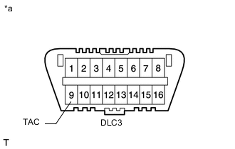
*a Front view of DLC3 When not using the GTS:
-
Connect a tester probe of a tachometer to terminal 9 (TAC) of the DLC3 with SST.
- SST
- 09843-18040
-
Start the engine and idle it.
-
-
Inspect the engine idle speed.
Standard idle speed 700 to 800 rpm Note
-
Turn all the electrical systems and A/C off.
-
When checking the idle speed, move the shift lever to neutral.
-
-
Turn the ignition switch off.
-
Disconnect the GTS or tachometer tester probe from the DLC3.
-
-
INSPECT MAXIMUM ENGINE SPEED
-
Start the engine.
-
Fully depress the accelerator pedal.
-
Check the maximum engine speed.
Maximum engine speed 4450 to 4750 rpm
-
-
INSPECT CYLINDER COMPRESSION PRESSURE
Tech Tips
Measure the compression pressure if the engine power is insufficient, oil is consumed excessively and/or fuel economy is poor.
-
Remove the 4 glow plug assemblies.
-
Disconnect the 4 connectors from the 4 injector assemblies.
-
Crank the engine to expel soot and other foreign matter from the inside of the cylinder.
-
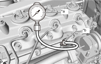
*a SST (Gauge Assembly) *b SST (Attachment H) Measure the compression pressure.
-
Install SST (attachment H) to the glow plug hole.
- SST
- 09992-19015 ( 09992-10110 )
- Torque:
- 13 N*m { 133 kgf*cm, 10 ft.*lbf }
-
Connect SST (gauge assembly) to SST (attachment H).
- SST
- 09992-19015 ( 09992-10010 )
-
Measure the compression pressure while cranking the engine.
Tech Tips
Always use a fully charged battery to obtain an engine speed of 250 rpm or more.
-
-
Perform the procedure above for each cylinder.
Standard compression pressure 2700 kPa (27.5 kgf/cm2, 392 psi) or higher Minimum pressure 2200 kPa (22.4 kgf/cm2, 319 psi) Standard difference between each cylinder 500 kPa (5.1 kgf/cm2, 73 psi) or less Note
This measurement must be done in as short a time as possible.
If the compression in one or more cylinders is low, add a small amount of engine oil into the glow plug hole. Then, repeat the procedure above for the low-compression cylinder(s).
Tech Tips
-
If poor compression improves after adding engine oil, the piston rings and/or cylinder bore may be worn or damaged.
-
If the pressure remains low, a valve may be stuck or seated improperly, or pressure may be dropping due to leakage through the gasket.
-
-
Remove SST (attachment and compression gauge).
-
Connect the 4 connectors to the 4 injector assemblies.
-
Install the 4 glow plug assemblies.
-