МАСЛЯНЫЙ НАСОС СНЯТИЕ

PROCEDURE
-
REMOVE ENGINE ASSEMBLY
-
INSTALL ENGINE TO ENGINE STAND
-
REMOVE VVT SENSOR (for Bank 1)
-
REMOVE VVT SENSOR (for Bank 2)
-
REMOVE CAMSHAFT TIMING OIL CONTROL VALVE ASSEMBLY (for Bank 1)
-
REMOVE CAMSHAFT TIMING OIL CONTROL VALVE ASSEMBLY (for Bank 2)
-
REMOVE IGNITION COIL ASSEMBLY
-
REMOVE ENGINE OIL LEVEL DIPSTICK GUIDE
-
REMOVE WATER INLET ASSEMBLY
-
REMOVE V-RIBBED BELT TENSIONER ASSEMBLY
-
REMOVE NO. 2 IDLER PULLEY SUB-ASSEMBLY
-
REMOVE NO. 1 IDLER PULLEY SUB-ASSEMBLY
-
REMOVE CRANKSHAFT PULLEY
-
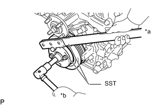
*a Hold *b Loosen Using SST, hold the crankshaft pulley and loosen the crankshaft pulley set bolt.
- SST
- 09213-54015 ( 91651-60855 )
- 09330-00021
-
Screw the crankshaft pulley set bolt into the crankshaft by 2 or 3 threads.
-
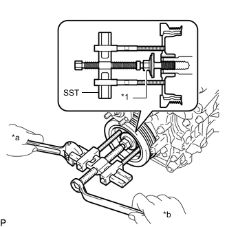
*1 Crankshaft Pulley Set Bolt *a Hold *b Turn Using the crankshaft pulley set bolt and SST, remove the crankshaft pulley and crankshaft pulley set bolt.
- SST
- 09950-50013 ( 09951-05010, 09952-05010, 09953-05020, 09954-05031 )
-
-
REMOVE NO. 2 OIL PAN SUB-ASSEMBLY
-
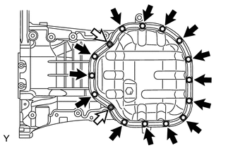

Bolt 
Nut Remove the 14 bolts and 2 nuts.
-
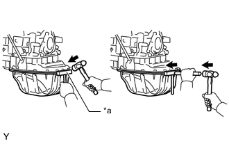
*a Oil Pan Seal Cutter Insert the blade of an oil pan seal cutter between the oil pan sub-assembly and No. 2 oil pan sub-assembly. Cut through the applied sealer and remove the No. 2 oil pan sub-assembly.
Note
-
Be careful not to damage the contact surfaces of the oil pan sub-assembly and No. 2 oil pan sub-assembly.
-
Be careful not to damage the flange of the No. 2 oil pan sub-assembly.
-
-
-
REMOVE OIL STRAINER SUB-ASSEMBLY
-
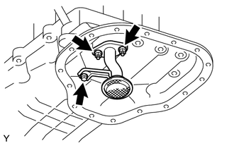
Remove the bolt, 2 nuts, oil strainer sub-assembly and gasket.
-
-
REMOVE OIL PAN SUB-ASSEMBLY
-
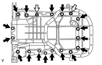
Bolt Nut Remove the 17 bolts and 2 nuts.
-
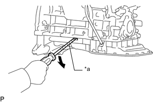
*a Protective Tape Using a screwdriver, remove the oil pan sub-assembly by prying between the oil pan sub-assembly and cylinder block as shown in the illustration.
Note
Be careful not to damage the contact surfaces of the cylinder block and oil pan sub-assembly.
Tech Tips
Tape the screwdriver tip before use.
-
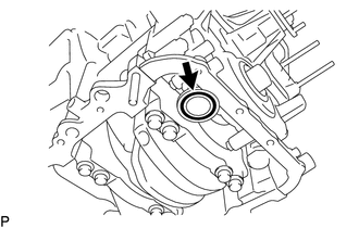
Remove the O-ring from the timing chain cover sub-assembly.
-
-
REMOVE NO. 1 FUEL PIPE SUB-ASSEMBLY AND NO. 2 FUEL PIPE SUB-ASSEMBLY
-
REMOVE CYLINDER HEAD COVER SUB-ASSEMBLY
-
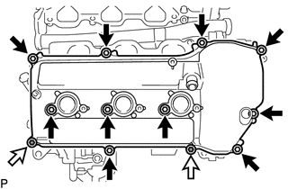
Bolt Nut Remove the 10 bolts, 3 seal washers, 2 nuts, cylinder head cover sub-assembly and cylinder head cover gasket.
-
-
REMOVE CYLINDER HEAD COVER SUB-ASSEMBLY LH
-
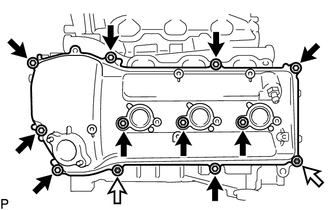
Bolt Nut Remove the 10 bolts, 3 seal washers, 2 nuts, cylinder head cover sub-assembly LH and cylinder head cover gasket.
-
-
REMOVE OIL FILTER SUB-ASSEMBLY
-
REMOVE OIL FILTER BRACKET SUB-ASSEMBLY
-
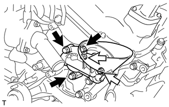
Bolt Nut Remove the 3 bolts, 2 nuts, oil filter bracket sub-assembly and gasket.
-
-
REMOVE TIMING CHAIN COVER SUB-ASSEMBLY
-
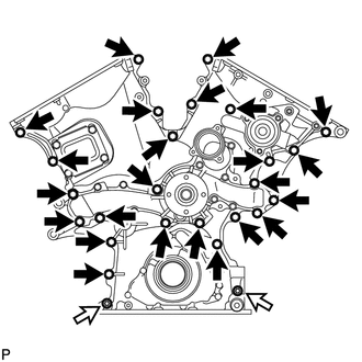
Bolt Nut Remove the 24 bolts and 2 nuts.
-
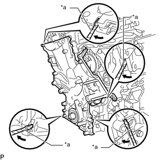
*a Protective Tape Remove the timing chain cover sub-assembly by prying between the timing chain cover sub-assembly and cylinder head sub-assembly or cylinder block sub-assembly with a screwdriver.
Note
Be careful not to damage the contact surfaces of the timing chain cover sub-assembly, cylinder block sub-assembly and cylinder head sub-assembly.
Tech Tips
Tape the screwdriver tip before use.
-
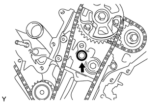
Remove the O-ring from the cylinder head LH.
-
-
REMOVE FRONT CRANKSHAFT OIL SEAL
-
Using a screwdriver and wooden block, pry out the front crankshaft oil seal.
Tech Tips
Tape the screwdriver tip before use.
Note
Do not damage the surface of the oil seal press fit hole and crankshaft.
-