РАДИАТОР УСТАНОВКА
PROCEDURE
-
INSTALL RADIATOR DRAIN COCK PLUG
-
Install a new O-ring to the radiator drain cock plug.
-
Install the radiator drain cock plug to the radiator assembly.
-
-
INSTALL RADIATOR ASSEMBLY
-
Set the radiator assembly to the vehicle.
-
Attach the 2 guides and 2 claws to connect the cooler condenser assembly to the radiator assembly.
Note
-
Do not apply any excessive force to the cooler condenser assembly and cooler pipe.
-
Do not allow the radiator assembly to interfere with other parts.
-
-
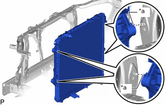
*a Claw Hook the claw of the radiator assembly as shown in the illustration.
-
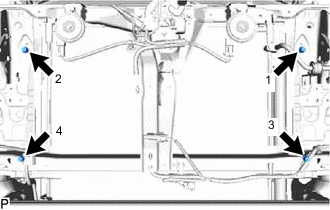
Install the radiator assembly with the 4 bolts in the order shown in the illustration.
- Torque:
- 22 N*m { 224 kgf*cm, 16 ft.*lbf }
-
-
INSTALL FAN SHROUD
-
Install a new clamp to the fan shroud.
-
Install the fan pulley to the engine water pump assembly.
-
Place the fan shroud together with the fluid coupling fan between the radiator assembly and engine.
Note
Be careful not to damage the radiator core.
-
Install the coupling fan to the engine water pump assembly with the 4 nuts. Tighten the nuts as much as possible by hand.
-
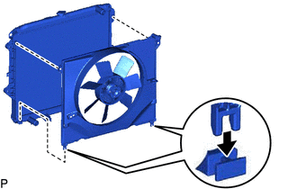
Attach the 2 guides and 2 claws of the fan shroud to the radiator as shown in the illustration.
-
Install the fan and generator V belt.
-
Tighten the 4 nuts of the fluid coupling fan.
- Torque:
- 25 N*m { 255 kgf*cm, 18 ft.*lbf }
-
Attach the 6 clamps to the radiator assembly and fan shroud to connect the wire harness.
-
-
INSTALL RADIATOR RESERVOIR
-
Install the radiator reservoir and grommet with the 2 bolts.
- Torque:
- 5.0 N*m { 51 kgf*cm, 44 in.*lbf }
-
Connect the reservoir hose to the radiator assembly.
-
-
CONNECT NO. 1 OIL COOLER INLET HOSE (for Automatic Transmission)
-
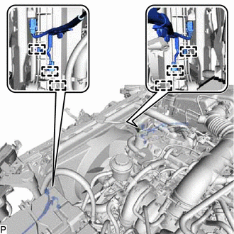
Connect the No. 1 oil cooler inlet hose to the radiator assembly, and slide the hose clamp to secure the hose.
Note
Connect the No. 1 oil cooler inlet hose to the radiator assembly so that the paint mark on the No. 1 oil cooler inlet hose is facing upwards.
-
-
CONNECT NO. 1 OIL COOLER OUTLET HOSE (for Automatic Transmission)
-
Connect the No. 1 oil cooler outlet hose to the radiator assembly, and slide the hose clamp to secure the hose.
Note
Connect the No. 1 oil cooler outlet hose to the radiator assembly so that the paint mark on the No. 1 oil cooler outlet hose is facing upwards.
-
-
CONNECT AIR PUMP INLET (w/ Secondary Air Injection System)
-
INSTALL RADIATOR HOSE OUTLET
-
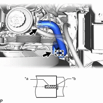
*a Paint Mark *b Protrusion Connect the radiator hose outlet to the radiator assembly and water inlet, and slide the 2 hose clamps to secure the hose.
Note
Connect the radiator hose outlet so that the paint mark on the radiator hose outlet is aligned with the protrusions of the radiator assembly and water inlet as shown in the illustration.
-
Attach the clamp to the radiator hose outlet.
-
-
INSTALL RADIATOR HOSE INLET
-
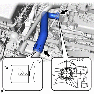
*a Paint Mark *b Protrusion *c Machined Edge Connect the radiator hose inlet to the radiator assembly and cylinder head, and slide the 2 hose clamps to secure the hose.
Note
Connect the radiator hose inlet so that the paint mark on the radiator hose inlet is aligned with the protrusion of the radiator assembly and the machined edge of the engine as shown in the illustration.
-
w/ Secondary Air Injection System:
Connect the hose clamp to the radiator hose inlet.
-
-
ADD ENGINE COOLANT
-
INSPECT FOR COOLANT LEAK
-
INSTALL NO. 1 RADIATOR AIR GUIDE
-
Install the No. 1 radiator air guide with 4 new clips.
-
-
INSTALL NO. 1 ENGINE UNDER COVER ASSEMBLY
-
INSTALL RADIATOR SIDE DEFLECTOR
-
for Resin Type Bumper:
-
for Steel Type Bumper:
-