НАСОС СИСТЕМЫ ОХЛАЖДЕНИЯ УСТАНОВКА
PROCEDURE
-
INSTALL ENGINE WATER PUMP ASSEMBLY
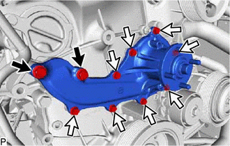

Bolt A 
Bolt B
-
Install a new gasket and the engine water pump assembly with the 10 bolts.
- Torque:
- for bolt A
- 25 N*m { 255 kgf*cm, 18 ft.*lbf }
- for bolt B
- 13 N*m { 133 kgf*cm, 10 ft.*lbf }
Note
Make sure that there is no oil on the threads of bolts A.
-
-
INSTALL V-RIBBED BELT TENSIONER ASSEMBLY
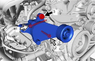
Bolt A Bolt B 
Bolt C
-
Temporarily install the V-ribbed belt tensioner assembly with the 3 bolts.
Tech Tips
Make sure the flanges of the bolts are contacting the tensioner surface.
-
Install the V-ribbed belt tensioner assembly by tightening the 3 bolts in the order shown in the illustration.
- Torque:
- for bolt A
- 43 N*m { 438 kgf*cm, 32 ft.*lbf }
- for bolt B
- 40 N*m { 408 kgf*cm, 30 ft.*lbf }
- for bolt C
- 23 N*m { 235 kgf*cm, 17 ft.*lbf }
-
-
INSTALL NO. 1 IDLER PULLEY SUB-ASSEMBLY
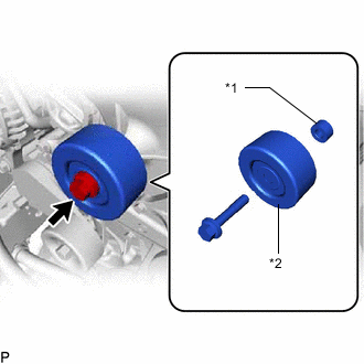
*1 Spacer *2 No. 1 Idler Pulley Sub-assembly
-
Install the spacer and No. 1 idler pulley sub-assembly with the bolt.
- Torque:
- 43 N*m { 438 kgf*cm, 32 ft.*lbf }
-
-
INSTALL ENGINE OIL LEVEL DIPSTICK GUIDE
-
Install a new O-ring and the engine oil level dipstick guide with the bolt.
- Torque:
- 8.0 N*m { 82 kgf*cm, 71 in.*lbf }
-
Install the engine oil level dipstick.
-
-
INSTALL GENERATOR ASSEMBLY
-
INSTALL FAN SHROUD
-
INSTALL RADIATOR RESERVOIR
-
INSTALL RADIATOR HOSE OUTLET
-
INSTALL RADIATOR HOSE INLET
-
ADD ENGINE COOLANT
-
INSPECT FOR COOLANT LEAK
-
INSTALL NO. 1 ENGINE UNDER COVER ASSEMBLY