СИСТЕМА ECD VC Output Circuit
DESCRIPTION
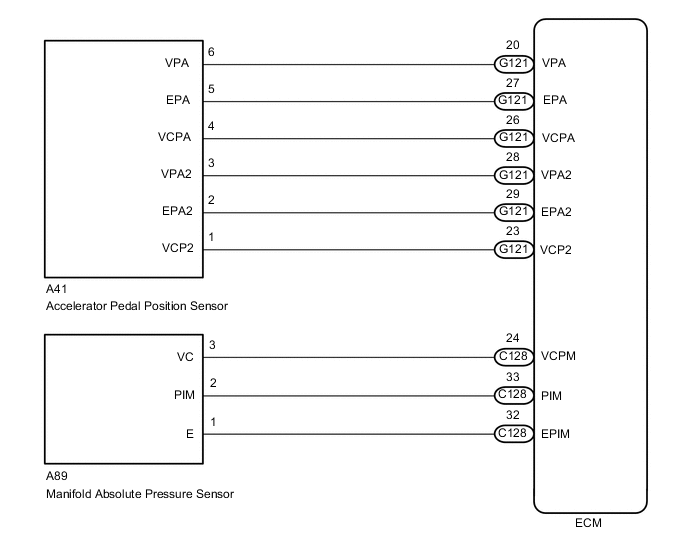
The VC voltage (5 V) is generated in the ECM. The voltage is used to supply power to the manifold absolute pressure sensor and accelerator pedal position sensor.
WIRING DIAGRAM
-
For the circuit diagram of the ECM power source circuit.
-
VC Power Source Circuit
CAUTION / NOTICE / HINT
Note
Check the fuses for circuits related to this system before performing the following inspection procedure.
PROCEDURE
-
CHECK CONNECTION BETWEEN GTS AND ECM
-
Connect the GTS to the DLC3.
-
Turn the ignition switch to ON and GTS on.
-
Check the communication between the GTS and ECM.
Result Condition Proceed to Communication is not possible A Communication is possible B
B 
GO TO MIL CIRCUIT Click here
A 
-
-
CHECK TERMINAL VOLTAGE (POWER SOURCE OF ECM)
-
Turn the ignition switch to ON.
-
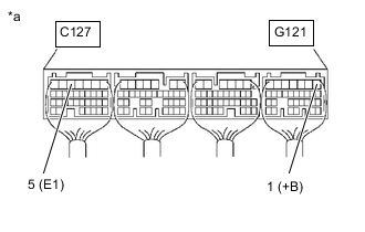
*a Component with harness connected
(ECM)
Measure the voltage according to the value(s) in the table below.
Standard Voltage Tester Connection Condition Specified Condition G121-1 (+B) - C127-5 (E1) IG ON 11 to 14 V Tech Tips
If the result is not as specified, since current is not flowing to the +B terminals of the ECM, the system may not be started.
Result Proceed to OK NG
NG
GO TO ECM POWER SOURCE CIRCUIT Click here
OK
-
-
CHECK CONNECTION BETWEEN GTS AND ECM (ACCELERATOR PEDAL POSITION SENSOR)
-
Disconnect the accelerator pedal position sensor connector.
-
Turn the ignition switch to ON.
-
Turn the GTS on.
-
Check the communication between the GTS and ECM.
Tech Tips
It can be checked using the "Engine" item of the Data List.
Result Result Proceed to Communication is possible A Communication is not possible B -
Reconnect the accelerator pedal position sensor connector.
B
REPLACE ACCELERATOR PEDAL SENSOR ASSEMBLY Click here
A
-
-
CHECK CONNECTION BETWEEN GTS AND ECM (MANIFOLD ABSOLUTE PRESSURE SENSOR)
-
Disconnect the manifold absolute pressure sensor connector.
-
Turn the ignition switch to ON.
-
Turn the GTS on.
-
Check the communication between the GTS and ECM.
Tech Tips
It can be checked using the "Engine" item of the Data List.
Result Result Proceed to Communication is possible A Communication is not possible B -
Reconnect the manifold absolute pressure sensor connector.
B
REPLACE MANIFOLD ABSOLUTE PRESSURE SENSOR Click here
A
-
-
CHECK HARNESS AND CONNECTOR (ECM - BODY GROUND)
-
Disconnect the manifold absolute pressure sensor connector.
-
Disconnect the accelerator pedal position sensor connector.
-
Disconnect the ECM connectors.
-
Measure the resistance according to the value(s) in the table below.
Standard Resistance Tester Connection Condition Specified Condition C128-24 (VCPM) - Body ground and other terminals Always 10 kΩ or higher G121-26 (VCPA) - Body ground and other terminals Always 10 kΩ or higher G121-23 (VCP2) - Body ground and other terminals Always 10 kΩ or higher G121-1 (+B) - Body ground and other terminals Always 10 kΩ or higher -
Reconnect the manifold absolute pressure sensor connector.
-
Reconnect the accelerator pedal position sensor connector.
-
Reconnect the ECM connector.
Result Proceed to OK NG
OK
REPLACE ECM Click here
NG
REPAIR OR REPLACE HARNESS OR CONNECTOR
-