СИСТЕМА ECD, Diagnostic DTC:P1121
| DTC Code | DTC Name |
|---|---|
| P1121 | Throttle / Pedal Position Sensor/Coolant Flow Control Valve Position Sensor Circuit Stuck |
DESCRIPTION
Refer to DTC P1120
| DTC No. | Detection Item | DTC Detection Condition | Trouble Area | MIL | Memory |
|---|---|---|---|---|---|
| P1121 | Throttle / Pedal Position Sensor/Coolant Flow Control Valve Position Sensor Circuit Stuck |
Condition 1
Condition 2 |
|
Comes on | DTC stored |
CAUTION / NOTICE / HINT
Tech Tips
Read freeze frame data using the GTS. Freeze frame data records the engine condition when malfunctions are detected. When troubleshooting, freeze frame data can help determine if the vehicle was moving or stationary, if the engine was warmed up or not, and other data from the time the malfunction occurred.
PROCEDURE
-
READ VALUE USING GTS (ACCELERATOR POSITION)
-
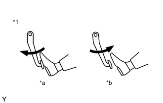
*1 Accelerator Pedal Assembly *a Depressed *b Released Connect the GTS to the DLC3.
-
Turn the ignition switch to ON and turn the GTS on.
-
Enter the following menus: Powertrain / Engine and ECT / Data List / Accel Sens. No.1 Volt % and Accel Sens. No.2 Volt %.
Powertrain > Engine > Data ListTester Display Accel Sens. No.1 Volt % Accel Sens. No.2 Volt % -
Read the values.
OK Check that the value displayed on the GTS changes by repeatedly depressing and releasing the accelerator pedal. Result Proceed to OK NG
OK 
REPLACE ECM Click here
NG 
-
-
CHECK HARNESS AND CONNECTOR (ECM - ACCELERATOR PEDAL POSITION SENSOR)
-
Disconnect the accelerator pedal position sensor connector.
-
Disconnect the ECM connector.
-
Measure the resistance according to the value(s) in the table below.
Standard resistance Tester Connection Condition Specified Condition A41-1 (VCP2) - G121-23 (VCP2) Always Below 1 Ω A41-2 (EPA2) - G121-29 (EPA2) Always Below 1 Ω A41-3 (VPA2) - G121-28 (VPA2) Always Below 1 Ω A41-4 (VCPA) - G121-26 (VCPA) Always Below 1 Ω A41-5 (EPA) - G121-27 (EPA) Always Below 1 Ω A41-6 (VPA) - G121-20 (VPA) Always Below 1 Ω A41-1 (VCP2) or G121-23 (VCP2) - Body ground and other terminals Always 10 kΩ or higher A41-2 (EPA2) or G121-29 (EPA2) - Body ground and other terminals Always 10 kΩ or higher A41-3 (VPA2) or G121-28 (VPA2) - Body ground and other terminals Always 10 kΩ or higher A41-4 (VCPA) or G121-26 (VCPA) - Body ground and other terminals Always 10 kΩ or higher A41-5 (EPA) or G121-27 (EPA) - Body ground and other terminals Always 10 kΩ or higher A41-6 (VPA) or G121-20 (VPA) - Body ground and other terminals Always 10 kΩ or higher Result Proceed to OK NG
OK
REPLACE ACCELERATOR PEDAL SENSOR ASSEMBLY Click here
NG
REPAIR OR REPLACE HARNESS OR CONNECTOR
-