БЛОК ДВИГАТЕЛЯ РАЗБОРКА

CAUTION / NOTICE / HINT
Note
-
When replacing the parts in the following chart (A), replace the No. 1 injection pipe sub-assembly, No. 2 injection pipe sub-assembly, No. 3 injection pipe sub-assembly, No. 4 injection pipe sub-assembly and/or fuel inlet pipe sub-assembly with new ones.
Replaced Parts (A) Pipes Requiring New Replacement
-
Injector assembly (including shuffling the injector assemblies between the cylinders)
-
Common rail assembly
-
Cylinder head sub-assembly
-
No. 1 injection pipe sub-assembly
-
No. 2 injection pipe sub-assembly
-
No. 3 injection pipe sub-assembly
-
No. 4 injection pipe sub-assembly
-
Supply pump assembly
-
Common rail assembly
-
Cylinder block sub-assembly
-
Cylinder head sub-assembly
-
Cylinder head gasket
-
Timing Gear Case Assembly
Fuel inlet pipe sub-assembly -
-
After removing the No. 1 injection pipe sub-assembly, No. 2 injection pipe sub-assembly, No. 3 injection pipe sub-assembly, No. 4 injection pipe sub-assembly and fuel inlet pipe sub-assembly, clean them with a brush and compressed air.
PROCEDURE
-
REMOVE OIL FILLER CAP SUB-ASSEMBLY
-
REMOVE CYLINDER HEAD COVER SUB-ASSEMBLY
-
REMOVE INJECTOR ASSEMBLY
-
REMOVE CAMSHAFT TIMING PULLEY
-
REMOVE NO. 2 TIMING BELT COVER
-
REMOVE CAMSHAFT SUB-ASSEMBLY
-
REMOVE VALVE LIFTER
-
Remove the valve lifters from the cylinder head sub-assembly.
Tech Tips
Arrange the valve lifters in the correct order.
-
-
REMOVE CYLINDER HEAD SUB-ASSEMBLY
-
REMOVE CYLINDER HEAD GASKET
-
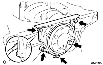
REMOVE ENGINE WATER PUMP ASSEMBLY
-
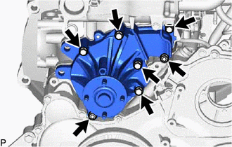
Remove the 5 bolts, 2 nuts, engine water pump assembly and gasket from the cylinder block sub-assembly.
-
-
REMOVE TIMING GEAR COVER
Note
As the fuel supply pump assembly is not installed, the injection gear is loose inside the timing gear case assembly. Do not allow the injection gear to fall.
Tech Tips
To prevent the injection gear from falling, temporarily install the fuel supply pump assembly.
-
Remove the bolt and No. 1 vacuum transmitting pipe.
-
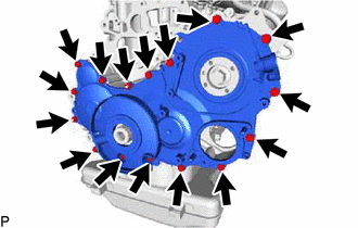
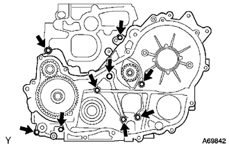
Remove the 14 bolts and 2 nuts.
-
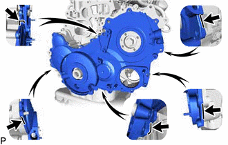
Pry the timing gear cover at the locations shown in the illustration and remove the timing gear cover.
Note
Be careful not to drop the injection gear.
-
Remove the O-ring from the timing gear case assembly.
-
-
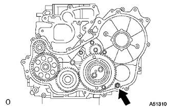
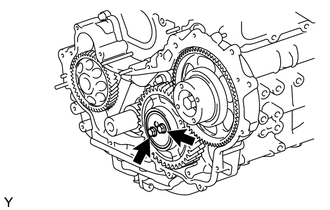
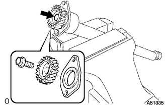
REMOVE INJECTION GEAR
-
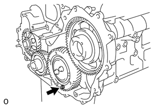
Secure the No. 2 idle sub gear to the No. 1 idle gear with a service bolt.
- Torque:
- 8.0 N*m { 82 kgf*cm, 71 in.*lbf }
Note
If the bolt hole of the No. 2 idle sub gear is not aligned with the bolt hole of the No. 1 idle gear, rotate the crankshaft counterclockwise to align the bolt holes. Then install the service bolt.
-
Remove the injection gear from the timing gear case assembly.
-
-
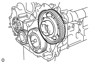
REMOVE NO. 1 CRANKSHAFT POSITION SENSOR PLATE
-
Remove the No. 1 crankshaft position sensor plate from the crankshaft.
-
-
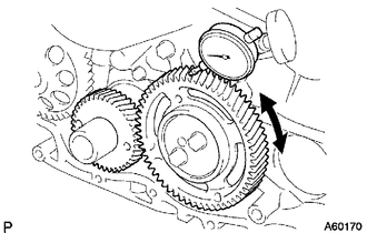
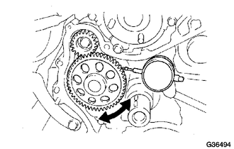
INSPECT BACKLASH OF CRANKSHAFT TIMING GEAR TO OIL PUMP GEAR
-
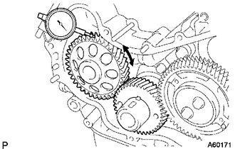
Using a dial indicator, measure the backlash.
Standard gear backlash 0.02 to 0.15 mm (0.000787 to 0.00591 in.) Maximum gear backlash 0.2 mm (0.00787 in.) If the gear backlash is more than the maximum, replace the crankshaft timing gear or timing gear case assembly.
-
-
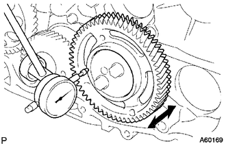
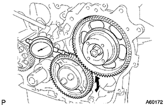
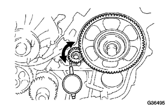
INSPECT BACKLASH OF CRANKSHAFT TIMING GEAR TO NO. 1 IDLE GEAR
-
Using a dial indicator, measure the backlash.
Standard gear backlash 0.02 to 0.15 mm (0.000787 to 0.00591 in.) Maximum gear backlash 0.2 mm (0.00787 in.) If the gear backlash is more than the maximum, replace the crankshaft timing gear or No. 1 idle gear.
-
-
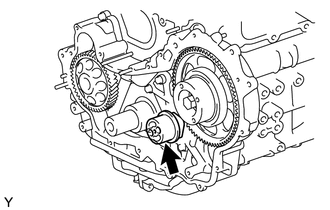
INSPECT NO. 1 IDLE GEAR THRUST CLEARANCE
-
Using a dial indicator, measure the thrust clearance.
Standard thrust clearance 0.06 to 0.11 mm (0.00236 to 0.00433 in.) Maximum thrust clearance 0.3 mm (0.0118 in.) If the thrust clearance is more than the maximum, replace the idle gear thrust plate. If necessary, replace the No. 1 idle gear or No. 1 idle gear shaft.
-
-
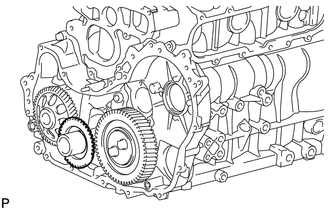
REMOVE CRANKSHAFT TIMING GEAR
-
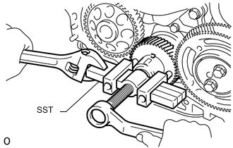
Using SST, remove the crankshaft timing gear from the crankshaft.
- SST
- 09950-50013 ( 09951-05010, 09952-05010, 09953-05010, 09954-05021 )
-
-
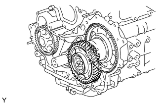
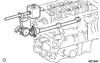
INSPECT BACKLASH OF INJECTION GEAR TO NO. 1 IDLE GEAR
-
Install the fuel supply pump assembly with the 2 nuts.
- Torque:
- 21 N*m { 214 kgf*cm, 15 ft.*lbf }
-
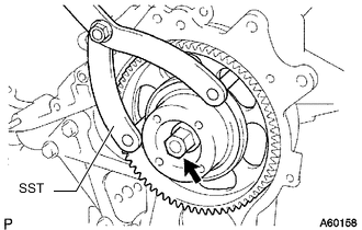
Using SST, install the injection gear with the nut.
- SST
- 09960-10010 ( 09962-01000, 09963-01000 )
- Torque:
- 63.7 N*m { 650 kgf*cm, 47 ft.*lbf }
-
Using a dial indicator, measure the backlash.
Standard gear backlash 0.02 to 0.15 mm (0.000787 to 0.00591 in.) Maximum gear backlash 0.2 mm (0.00787 in.) If the gear backlash is more than the maximum, replace the injection gear or No. 1 idle gear.
-
-
REMOVE IDLE GEAR THRUST PLATE
-
Remove the 2 bolts and idle gear thrust plate from the No. 1 idle gear shaft.
-
-
REMOVE NO. 1 IDLE GEAR
-
Remove the No. 1 idle gear together with the No. 2 idle sub gear from the No. 1 idle gear shaft.
-
-
REMOVE NO. 1 IDLE GEAR SHAFT
-
Remove the No. 1 idle gear shaft from the timing gear case assembly.
-
-
INSPECT BACKLASH OF NO. 1 BALANCESHAFT TO OIL PUMP GEAR
-
Using a dial indicator, measure the backlash.
Standard gear backlash 0.02 to 0.15 mm (0.000787 to 0.00591 in.) Maximum gear backlash 0.2 mm (0.00787 in.) If the gear backlash is more than the maximum, replace the No. 1 balanceshaft sub-assembly or timing gear case assembly.
-
-
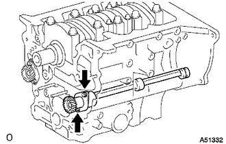
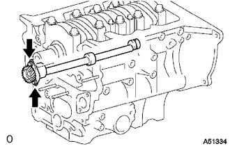
INSPECT BACKLASH OF NO. 2 BALANCESHAFT TO INJECTION GEAR
-
Using a dial indicator, measure the backlash.
Standard gear backlash 0.02 to 0.15 mm (0.000787 to 0.00591 in.) Maximum gear backlash 0.2 mm (0.00787 in.) If the gear backlash is more than the maximum, replace the No. 2 balanceshaft assembly or injection gear.
-
Using SST, remove the nut and injection gear.
- SST
- 09960-10010 ( 09962-01000, 09963-01000 )
-
Remove the 2 nuts and fuel supply pump assembly.
-
Remove the gears and timing gear case.
-
-
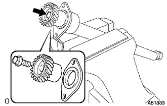
REMOVE NO. 1 IDLE SUB GEAR
-
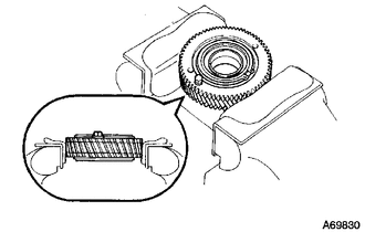
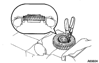
Mount the No. 1 idle gear and No. 2 idle sub gear in a vise.
Note
Be careful not to damage the gears.
-
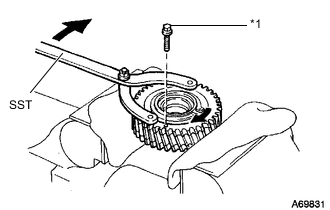
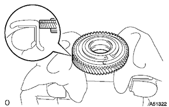
*1 Service Bolt Using SST, turn the No. 1 idle sub gear clockwise and remove the service bolt.
- SST
- 09960-10010 ( 09962-01000, 09963-00600 )
-
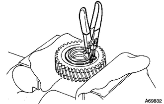
Using snap ring pliers, remove the snap ring.
-
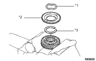
*1 Wave Washer *2 No. 1 Idle Sub Gear *3 Idle Gear Spring Remove the wave washer, No. 1 idle sub gear and idle gear spring.
-
-
REMOVE NO. 2 IDLE SUB GEAR
-
Turn the No. 1 idle gear over and set it in a vise.
Note
Be careful not a damage the gear.
-
Using snap ring pliers, remove the snap ring.
-
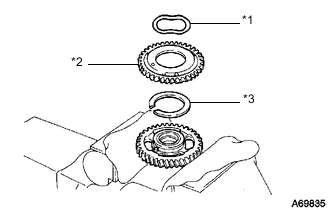
*1 Wave Washer *2 No. 2 Idle Sub Gear *3 Idle Gear Spring Remove the wave washer, No. 2 idle sub gear and idle gear spring.
-
-
REMOVE OIL PAN SUB-ASSEMBLY
-
Remove the 22 bolts and 2 nuts.
-
Insert the blade of an oil pan seal cutter between the oil pan sub-assembly and cylinder block sub-assembly, cut through the applied sealer and remove the oil pan sub-assembly from the cylinder block sub-assembly.
Note
-
Do not use the oil pan seal cutter for the area between the oil pan sub-assembly and timing gear case assembly, or for the area between the oil pan sub-assembly and rear oil seal retainer.
-
Be careful not to damage the oil pan sub-assembly flange.
-
-
-
REMOVE OIL STRAINER SUB-ASSEMBLY
-
Remove the 2 bolts, 2 nuts, oil strainer sub-assembly and gasket from the cylinder block sub-assembly.
-
-
REMOVE TIMING GEAR CASE ASSEMBLY
-
Remove the union bolt and 8 bolts.
-
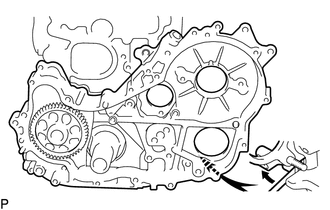
Pry the timing gear case assembly at the location shown in the illustration and remove the timing gear case assembly and gasket from the cylinder block sub-assembly.
-
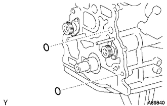
Remove the 2 O-rings from the cylinder block sub-assembly.
-
-
INSPECT NO. 1 BALANCESHAFT THRUST CLEARANCE
-
Using a dial indicator, measure the thrust clearance while moving the No. 1 balanceshaft sub-assembly back and forth.
Standard thrust clearance 0.065 to 0.140 mm (0.00256 to 0.00551 in.) Maximum thrust clearance 0.25 mm (0.00984 in.) If the thrust clearance is more than the maximum clearance, replace the balanceshaft thrust washer.
If the thrust clearance is still more than the maximum clearance, replace the No. 1 balanceshaft sub-assembly.
-
-
REMOVE NO.1 BALANCESHAFT SUB-ASSEMBLY
-
Remove the 2 bolts and No. 1 balanceshaft sub-assembly from the cylinder block sub-assembly.
-
-
REMOVE NO. 1 BALANCESHAFT DRIVEN GEAR
-
Mount the No. 1 balanceshaft sub-assembly between aluminum plates in a vise.
Note
Be careful not to damage the No. 1 balanceshaft sub-assembly.
-
Remove the bolt, No. 1 balanceshaft driven gear and balanceshaft thrust washer from the No. 1 balanceshaft sub-assembly.
-
-
INSPECT NO. 2 BALANCESHAFT THRUST CLEARANCE
-
Using a dial indicator, measure the thrust clearance while moving the No. 2 balanceshaft sub-assembly back and forth.
Standard thrust clearance 0.065 to 0.140 mm (0.00256 to 0.00551 in.) Maximum thrust clearance 0.25 mm (0.00984 in.) If the thrust clearance is more than the maximum clearance, replace the balanceshaft thrust washer.
If the thrust clearance is still more than the maximum clearance, replace the No. 2 balanceshaft sub-assembly.
-
-
REMOVE NO. 2 BALANCESHAFT SUB-ASSEMBLY
-
Remove the 2 bolts and No. 2 balanceshaft sub-assembly from the cylinder block sub-assembly.
-
-
REMOVE NO. 2 BALANCESHAFT DRIVEN GEAR
-
Mount the No. 2 balanceshaft sub-assembly between aluminum plates in a vise.
Note
Be careful not to damage the No. 2 balanceshaft sub-assembly.
-
Remove the bolt, No. 2 balanceshaft driven gear and balanceshaft thrust washer from the No. 2 balanceshaft sub-assembly.
-
-
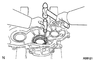
REMOVE REAR ENGINE OIL SEAL RETAINER
-
Remove the 5 bolts.
-
Using a screwdriver, remove the rear engine oil seal retainer by prying between the rear engine oil seal retainer and cylinder block sub-assembly.
-
-
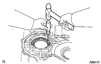
REMOVE REAR ENGINE OIL SEAL
-
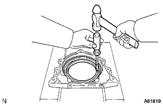
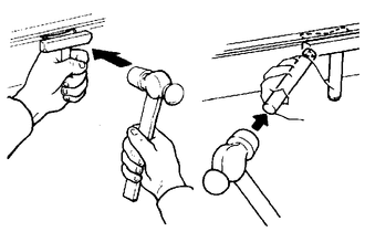
Using a screwdriver and hammer, tap out the rear engine oil seal from the rear engine oil seal retainer.
-
-
REMOVE FRONT CRANKSHAFT OIL SEAL
-
Using a screwdriver and hammer, tap out the front crankshaft oil seal from the timing gear cover.
-
-
REMOVE INJECTION PUMP OIL SEAL
-
Using a screwdriver and hammer, tap out the injection pump oil seal from the timing gear cover.
-