РАСПРЕДВАЛ СНЯТИЕ

CAUTION / NOTICE / HINT
The necessary procedures (adjustment, calibration, initialization, or registration) that must be performed after parts are removed, installed, or replaced during the camshaft sub-assembly removal/installation are shown below.
| Replacement Part or Procedure | Necessary Procedures | Effects/Inoperative when not Performed | Link |
|---|---|---|---|
| Replacement of injector assembly |
|
Engine starting | |
| Replacement of timing belt | Mode reset operation |
|
CAUTION:
To prevent burns, do not touch the engine, exhaust manifold or other high temperature components while the engine is hot.
Note
-
When replacing the parts in the following chart (A), replace the No. 1 injection pipe sub-assembly, No. 2 injection pipe sub-assembly, No. 3 injection pipe sub-assembly, No. 4 injection pipe sub-assembly and/or fuel inlet pipe sub-assembly with new ones.
Replaced Parts (A) Pipes Requiring New Replacement
-
Injector assembly (including shuffling the injector assemblies between the cylinders)
-
Common rail assembly
-
Cylinder head sub-assembly
-
No. 1 injection pipe sub-assembly
-
No. 2 injection pipe sub-assembly
-
No. 3 injection pipe sub-assembly
-
No. 4 injection pipe sub-assembly
-
Supply pump assembly
-
Common rail assembly
-
Cylinder block sub-assembly
-
Cylinder head sub-assembly
-
Cylinder head gasket
-
Timing Gear Case Assembly
Fuel inlet pipe sub-assembly -
-
After removing the No. 1 injection pipe sub-assembly, No. 2 injection pipe sub-assembly, No. 3 injection pipe sub-assembly, No. 4 injection pipe sub-assembly and fuel inlet pipe sub-assembly, clean them with a brush and compressed air.
PROCEDURE
-
REMOVE NO. 1 ENGINE UNDER COVER ASSEMBLY
-
DRAIN ENGINE COOLANT
-
DRAIN ENGINE OIL
-
REMOVE NO. 1 RADIATOR HOSE
-
REMOVE FAN SHROUD
-
REMOVE NO. 1 ENGINE COVER SUB-ASSEMBLY
-
REMOVE MANIFOLD ABSOLUTE PRESSURE SENSOR
-
REMOVE INTAKE AIR TEMPERATURE SENSOR
-
REMOVE INTERCOOLER ASSEMBLY
-
REMOVE NO. 1, NO. 2 AND NO. 3 INJECTION PIPE SUB-ASSEMBLY
-
REMOVE NO. 4 INJECTION PIPE SUB-ASSEMBLY
-
REMOVE NO. 2 NOZZLE LEAKAGE PIPE ASSEMBLY
-
REMOVE CYLINDER HEAD COVER SUB-ASSEMBLY
-
REMOVE INJECTOR ASSEMBLY
-
REMOVE NO. 1 TIMING BELT COVER
-
REMOVE TIMING BELT
-
REMOVE NO. 1 TIMING BELT IDLER SUB-ASSEMBLY
-
REMOVE CAMSHAFT TIMING PULLEY
-
REMOVE NO. 2 TIMING BELT COVER
-
REMOVE CAMSHAFT SUB-ASSEMBLY
-
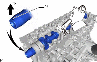
*a Key Groove *b Upward Turn the intake camshaft sub-assembly with a wrench so that the key groove of the camshaft sub-assembly faces upward.
-
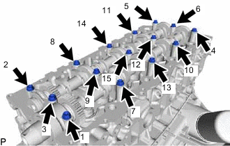
Uniformly loosen the 15 camshaft bearing cap bolts in several passes in the sequence shown in the illustration.
-
Remove the 15 camshaft bearing cap bolts, No. 1 camshaft bearing cap, 3 No. 2 camshaft bearing caps, No. 3 camshaft bearing cap, camshaft oil seal and intake camshaft sub-assembly and exhaust camshaft sub-assembly from the cylinder head sub-assembly.
-