БЛОК ДВИГАТЕЛЯ ПОВТОРНАЯ СБОРКА

PROCEDURE
-
INSTALL STUD BOLT
Note
If a stud bolt is deformed or its threads are damaged, replace it.
-
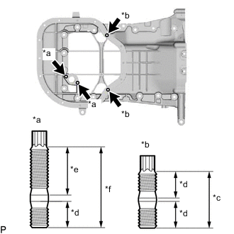
*a Bolt A *b Bolt B *c 19 mm (0.748 in.) *d 9 mm (0.354 in.) *e 16 mm (0.630 in.) *f 27 mm (1.06 in.) Install the oil pan sub-assembly stud bolt.
-
Using an E6 "TORX" wrench, install the 4 stud bolts.
- Torque:
- 4.0 N*m { 41 kgf*cm, 35 in.*lbf }
-
-
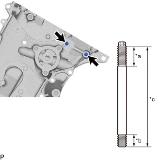
*a 18 mm (0.709 in.) *b 12 mm (0.472 in.) *c 93 mm (3.66 in.) Install the timing chain cover sub-assembly stud bolt.
-
Using an E8 "TORX" wrench, install the 2 stud bolts.
- Torque:
- 10 N*m { 102 kgf*cm, 7 ft.*lbf }
-
-
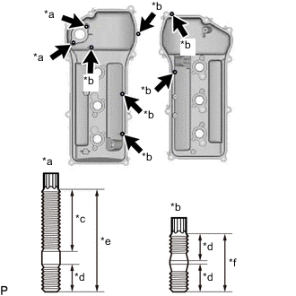
*a Bolt A *b Bolt B *c 21 mm (0.827 in.) *d 9 mm (0.354 in.) *e 34 mm (1.34 in.) *f 19 mm (0.748 in.) Install the cylinder head cover sub-assembly stud bolt.
-
Using an E6 "TORX" wrench, install the 8 stud bolts.
- Torque:
- 6.0 N*m { 61 kgf*cm, 53 in.*lbf }
-
-
-
INSTALL TAPER SCREW PLUG
-
Clean the taper screw plug and plug hole.
-
Apply adhesive to 2 or 3 threads of the taper screw plug end.
Adhesive Toyota Genuine Adhesive 1324, Three Bond 1324 or equivalent -
Install the taper screw plug.
- Torque:
- 25 N*m { 255 kgf*cm, 18 ft.*lbf }
Note
-
Install the taper screw plug within 3 minutes after applying adhesive.
-
Do not expose the taper screw plug to coolant within 1 hour of the installation.
-
-
INSTALL VALVE LIFTER
-
Apply engine oil to each valve stem and valve lifter, and then install the 24 valve lifters.
-
Check that the 24 valve lifters rotate smoothly by hand.
-
-
INSTALL KNOCK SENSOR
-
INSTALL NO. 1 WATER OUTLET PIPE
-
for Type A:
Install the No. 1 water outlet pipe with the 3 bolts.
- Torque:
- 10 N*m { 102 kgf*cm, 7 ft.*lbf }
-
for Type B:
Install the No. 1 water outlet pipe with the 2 nuts and bolt.
- Torque:
- 10 N*m { 102 kgf*cm, 7 ft.*lbf }
-
Install the knock sensor wire.
-
-
INSTALL NO. 2 CYLINDER HEAD GASKET
-
INSTALL CYLINDER HEAD LH
-
INSTALL CYLINDER HEAD GASKET
-
INSTALL CYLINDER HEAD SUB-ASSEMBLY
-
INSTALL NO. 4 CAMSHAFT SUB-ASSEMBLY
-
Apply new engine oil to the thrust portion and journals of the No. 4 camshaft sub-assembly.
-
Install the No. 4 camshaft sub-assembly to the cylinder head LH.
-
-
INSTALL NO. 3 CAMSHAFT SUB-ASSEMBLY
-
Apply new engine oil to the thrust portion and journals of the No. 3 camshaft sub-assembly.
-
Install the No. 3 camshaft sub-assembly to the cylinder head LH.
-
-
INSTALL CAMSHAFT BEARING CAP (for Bank 2)
Note
As the thrust clearance of the camshaft is small, the camshaft must be kept level while it is being installed. If the camshaft is not kept level, the portion of the cylinder head which receives the shaft thrust may crack or be damaged, causing the camshaft to seize or break. To avoid this, make sure the following steps are carried out.
-
Temporarily install the crankshaft pulley set bolt.
-

*1 Crankshaft Timing Gear Key *a Turn Turn the crankshaft and set the crankshaft timing gear key to the left horizontal position.
Note
Having the crankshaft at the wrong angle can cause the piston head and valve head to come into contact with each other when the camshaft is installed, causing damage. Always set the crankshaft to the correct angle.
-
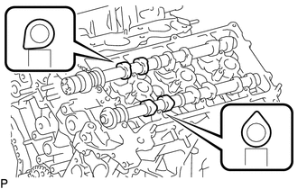
Set the No. 3 camshaft sub-assembly and No. 4 camshaft sub-assembly as shown in the illustration.
-
Check the numbers on the camshaft bearing caps and the installation direction before temporarily placing each cap.
-
Apply a light coat of engine oil to the threads and under the heads of the bolts.
-

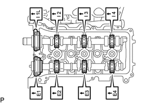
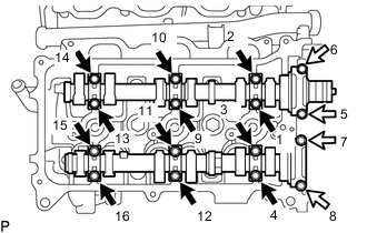
Bolt A 
Bolt B Install and uniformly tighten the 16 bolts in several steps in the order shown in the illustration.
- Torque:
- for bolt A
- 9.0 N*m { 92 kgf*cm, 80 in.*lbf }
- for bolt B
- 24 N*m { 245 kgf*cm, 18 ft.*lbf }
Standard Bolt Length Item Specified Condition Bolt A 39 mm (1.54 in.) Bolt B 50 mm (1.97 in.) -
Remove the crankshaft pulley set bolt.
-
-
INSTALL NO. 2 CAMSHAFT BEARING
-
Install the No. 2 camshaft bearing to the cylinder head sub-assembly.
Note
Clean the backside of the No. 2 camshaft bearing and the contact surface of the cylinder head sub-assembly and prevent oil from adhering to them.
-
-
INSTALL NO. 1 CAMSHAFT BEARING
-
*a Claw Align the claw of the No. 1 camshaft bearing with the groove of the camshaft bearing cap and push in the No. 1 camshaft bearing.
Note
-
Install the No. 1 camshaft bearing while aligning it with the oil hole in the camshaft bearing cap.
-
Clean the backside of the No. 1 camshaft bearing and the contact surface of the camshaft bearing cap and prevent oil from adhering to them.
-
-
-
INSTALL NO. 2 CAMSHAFT
-
Apply new engine oil to the thrust portion and journals of the No. 2 camshaft.
-
Install the No. 2 camshaft to the cylinder head sub-assembly.
-
-
INSTALL CAMSHAFT
-
Apply new engine oil to the thrust portion and journals of the camshaft.
-
Install the camshaft to the cylinder head sub-assembly.
-
-
INSTALL CAMSHAFT BEARING CAP (for Bank 1)
Note
As the thrust clearance of the camshaft is small, the camshaft must be kept level while it is being installed. If the camshaft is not kept level, the portion of the cylinder head which receives the shaft thrust may crack or be damaged, causing the camshaft to seize or break. To avoid this, make sure the following steps are carried out.
-
Temporarily install the crankshaft pulley set bolt.
-
*1 Crankshaft Timing Gear Key *a Turn Turn the crankshaft and set the crankshaft timing gear key to the left horizontal position.
Note
Having the crankshaft at the wrong angle can cause the piston head and valve head to come into contact with each other when the camshaft is installed, causing damage. Always set the crankshaft to the correct angle.
-
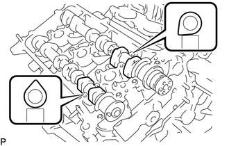
Set the camshaft and No. 2 camshaft as shown in the illustration.
-
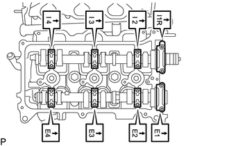
Check the numbers on the camshaft bearing caps and the installation direction before temporarily placing each cap.
-
Apply a light coat of engine oil to the threads and under the heads of the bolts.
-
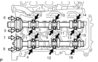
Bolt A Bolt B Install and uniformly tighten the 16 bolts in several steps in the order shown in the illustration.
- Torque:
- for bolt A
- 9.0 N*m { 92 kgf*cm, 80 in.*lbf }
- for bolt B
- 24 N*m { 245 kgf*cm, 18 ft.*lbf }
Standard Bolt Length Item Specified Condition Bolt A 39 mm (1.54 in.) Bolt B 50 mm (1.97 in.) -
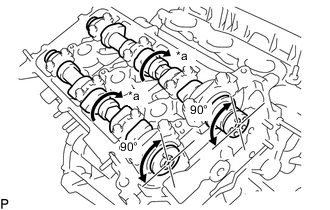
*a Turn Turn the camshafts clockwise until the camshaft knock pin is at a position 90° from the cylinder head sub-assembly.
-
Remove the crankshaft pulley set bolt.
-
-
INSTALL NO. 3 CHAIN TENSIONER ASSEMBLY
-
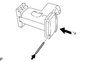
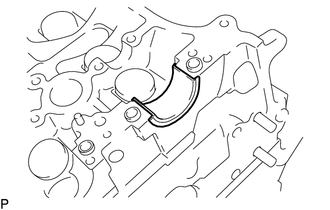
*a Push While pushing in the No. 3 chain tensioner assembly, insert a pin with a diameter of 1.0 mm (0.0394 in.) into the hole to fix the No. 3 chain tensioner assembly in place.
-
Install the No. 3 chain tensioner assembly with the bolt.
- Torque:
- 21 N*m { 214 kgf*cm, 15 ft.*lbf }
-
-
INSTALL CAMSHAFT TIMING GEARS AND NO. 2 CHAIN SUB-ASSEMBLY (for Bank 2)
-
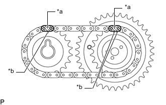
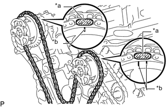
*a Mark Link (Yellow) *b Timing Mark Align the mark links (yellow) of the No. 2 chain sub-assembly with the timing marks of the camshaft timing gear assembly and camshaft timing sprocket.
-
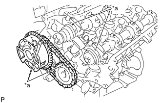
*a Timing Mark Align the timing marks on the camshaft timing gear assembly and camshaft timing sprocket with the timing marks on the camshaft bearing caps, and install the camshaft timing gear assembly and camshaft timing sprocket together with the No. 2 chain sub-assembly.
-
Temporarily install the camshaft timing gear assembly and camshaft timing sprocket with the 2 bolts.
Note
Do not push the camshaft timing gear assembly onto the No. 3 camshaft sub-assembly forcibly when installing it.
-
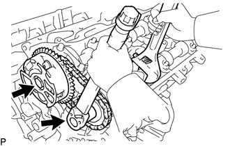
Hold the hexagonal portion of the No. 4 camshaft sub-assembly with a wrench and tighten the 2 bolts.
- Torque:
- 100 N*m { 1020 kgf*cm, 74 ft.*lbf }
-
Remove the pin from the No. 3 chain tensioner assembly.
-
-
INSTALL NO. 2 CHAIN TENSIONER ASSEMBLY
-
*a Push While pushing in the No. 2 chain tensioner assembly, insert a pin with a diameter of 1.0 mm (0.0394 in.) into the hole to fix the No. 2 chain tensioner assembly in place.
-
Install the No. 2 chain tensioner assembly with the bolt.
- Torque:
- 21 N*m { 214 kgf*cm, 15 ft.*lbf }
-
-
INSTALL CAMSHAFT TIMING GEARS AND NO. 2 CHAIN SUB-ASSEMBLY (for Bank 1)
-
*a Mark Link (Yellow) *b Timing Mark Align the mark links (yellow) of the No. 2 chain sub-assembly with the timing marks of the camshaft timing gear assembly and camshaft timing sprocket.
-
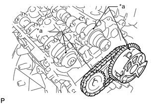
*a Timing Mark Align the timing marks on the camshaft timing gear assembly and camshaft timing sprocket with the timing marks on the camshaft bearing caps, and install the camshaft timing gear assembly and camshaft timing sprocket together with the No. 2 chain sub-assembly.
-
Temporarily install the camshaft timing gear assembly and camshaft timing sprocket with the 2 bolts.
Note
Do not push the camshaft timing gear assembly onto the camshaft forcibly when installing it.
-
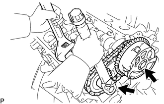
Hold the hexagonal portion of the No. 2 camshaft with a wrench and tighten the 2 bolts.
- Torque:
- 100 N*m { 1020 kgf*cm, 74 ft.*lbf }
-
Remove the pin from the No. 2 chain tensioner assembly.
-
-
INSTALL NO. 1 CHAIN VIBRATION DAMPER
-
Install the No. 1 chain vibration damper with the 2 bolts.
- Torque:
- 19 N*m { 194 kgf*cm, 14 ft.*lbf }
-
-
INSTALL CRANKSHAFT TIMING SPROCKET
-
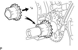
*a Inward Align the crankshaft timing gear key with the groove of the crankshaft timing sprocket and install the crankshaft timing sprocket as shown in the illustration.
-
-
INSTALL CHAIN TENSIONER SLIPPER
-
INSTALL NO. 1 CHAIN TENSIONER ASSEMBLY
-
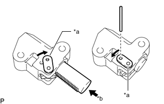
*a Stopper Plate *b Push While turning the stopper plate of the No. 1 chain tensioner assembly clockwise, push in the plunger of the No. 1 chain tensioner assembly as shown in the illustration.
-
While turning the stopper plate of the No. 1 chain tensioner assembly counterclockwise, insert a bar with a diameter of 3.5 mm (0.138 in.) into the holes in the stopper plate and No. 1 chain tensioner assembly to fix the stopper plate in place.
-
Install the No. 1 chain tensioner assembly with the 2 bolts.
- Torque:
- 10 N*m { 102 kgf*cm, 7 ft.*lbf }
-
-
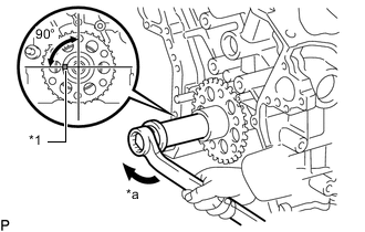
SET NO. 1 CYLINDER TO TDC/COMPRESSION
-
Set the No. 1 cylinder to TDC/compression.
-
Align the timing marks of the camshaft timing gear assemblies and camshaft timing sprockets with the timing marks of the camshaft bearing caps.
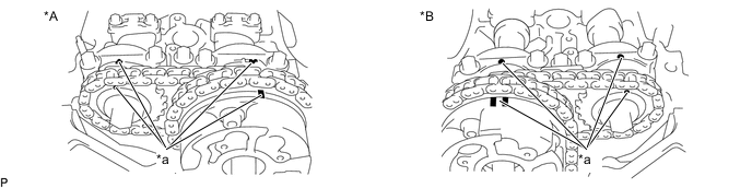
*A for Bank 1 *B for Bank 2 *a Timing Mark - - -
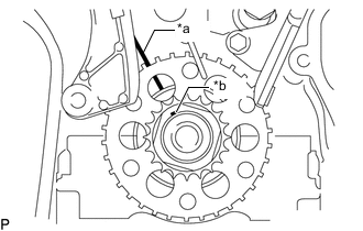
*a Timing Line *b Crankshaft Timing Gear Key Temporarily install the crankshaft pulley set bolt and turn the crankshaft to align the crankshaft timing gear key with the timing line of the cylinder block sub-assembly.
-
-
-
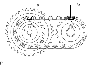
INSTALL CHAIN SUB-ASSEMBLY
-
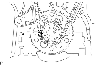
*a Mark Link (Yellow) *b Timing Mark Align the mark link (yellow) of the chain sub-assembly with the timing mark of the crankshaft timing sprocket.
-
*a Mark Link (Orange) *b Timing Mark Align the mark links (orange) of the chain sub-assembly with the timing marks of the camshaft timing gear assemblies and install the chain sub-assembly.
-
-
INSTALL NO. 2 CHAIN VIBRATION DAMPER
-
Install the 2 No. 2 chain vibration dampers.
-
-
INSTALL IDLE SPROCKET ASSEMBLY
-
Apply a light coat of engine oil to the rotating surface of the No. 1 idle gear shaft.
Tech Tips
Check for foreign matter on the No. 1 idle gear shaft and No. 2 idle gear shaft.
-
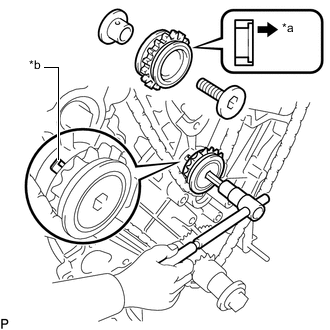
*a Forward *b Knock Pin Temporarily install the No. 1 idle gear shaft and idle sprocket assembly together with the No. 2 idle gear shaft while aligning the knock pin of the No. 1 idle gear shaft with the knock pin groove of the cylinder block sub-assembly.
Note
Make sure the idle sprocket assembly is installed facing the proper direction.
-
Using a 10 mm hexagon wrench, tighten the No. 2 idle gear shaft.
- Torque:
- 60 N*m { 612 kgf*cm, 44 ft.*lbf }
-
Remove the bar from the No. 1 chain tensioner assembly.
-
-
INSTALL ENGINE WATER PUMP ASSEMBLY
-
Install a new gasket and the engine water pump assembly with the 8 bolts.
- Torque:
- 11 N*m { 112 kgf*cm, 8 ft.*lbf }
-
-
INSTALL TIMING CHAIN COVER SUB-ASSEMBLY
-
INSTALL FRONT CRANKSHAFT OIL SEAL
-
INSTALL TIMING CHAIN COVER PLATE
-
INSTALL REAR CRANKSHAFT OIL SEAL
-
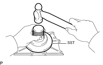
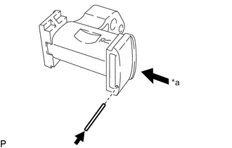
Using SST and a hammer, tap in a new rear crankshaft oil seal until its surface is flush with the engine rear oil seal retainer edge.
- SST
- 09223-78010
-
Apply MP grease to the lip of the rear crankshaft oil seal.
-
-
INSTALL ENGINE REAR OIL SEAL RETAINER
-
Clean and degrease the contact surfaces of the engine rear oil seal retainer and cylinder block.
-
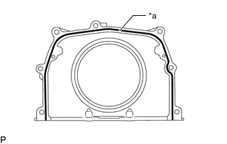
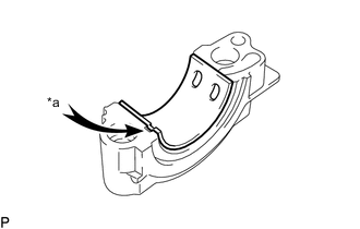
*a Seal Packing Application Area Apply seal packing as shown in the illustration.
Seal packing Toyota Genuine Seal Packing Black, Three Bond 1207B or equivalent Standard seal diameter 2.0 to 3.0 mm (0.0787 to 0.118 in.) Note
Parts must be assembled within 3 minutes of application. Otherwise the seal packing must be removed and reapplied.
-
Install the engine rear oil seal retainer with the 5 bolts and 2 nuts.
- Torque:
- for nut
- 9.0 N*m { 92 kgf*cm, 80 in.*lbf }
- for bolt
- 10 N*m { 102 kgf*cm, 7 ft.*lbf }
-
-
INSTALL OIL PAN SUB-ASSEMBLY
-
INSTALL OIL STRAINER SUB-ASSEMBLY
-
INSTALL NO. 2 OIL PAN SUB-ASSEMBLY
-
INSTALL OIL PAN DRAIN PLUG
-
Install a new gasket and the oil pan drain plug.
- Torque:
- 40 N*m { 408 kgf*cm, 30 ft.*lbf }
-
-
INSTALL CRANKSHAFT PULLEY
-
SET NO. 1 CYLINDER TO TDC/COMPRESSION
-
INSPECT VALVE CLEARANCE
-
ADJUST VALVE CLEARANCE
-
INSTALL CYLINDER HEAD COVER SUB-ASSEMBLY LH
-
INSTALL PCV VALVE SUB-ASSEMBLY
-
INSTALL CYLINDER HEAD COVER SUB-ASSEMBLY
-
INSTALL SPARK PLUG
-
INSTALL OIL FILLER CAP HOUSING
-
*1 Gasket Install a new gasket and the oil filler cap housing with the 2 nuts.
- Torque:
- 9.0 N*m { 92 kgf*cm, 80 in.*lbf }
-
-
INSTALL OIL FILLER CAP SUB-ASSEMBLY
-
Install the gasket to the oil filler cap sub-assembly.
-
Install the oil filler cap sub-assembly.
-
-
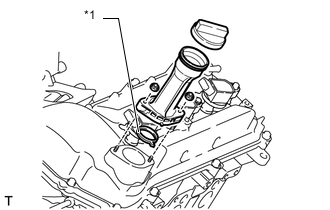
INSTALL REAR WATER BY-PASS JOINT
-
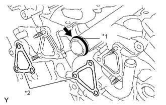
*1 O-Ring *2 Gasket Apply soapy water to a new O-ring and install it to the No. 1 water outlet pipe. Then install 2 new gaskets to the water ports LH and RH.
-
Install the rear water by-pass joint with the 2 bolts and 4 nuts.
- Torque:
- for bolt
- 10 N*m { 102 kgf*cm, 7 ft.*lbf }
- for nut
- 9.0 N*m { 92 kgf*cm, 80 in.*lbf }
-
-
INSTALL WATER INLET ASSEMBLY
-
INSTALL OIL FILTER BRACKET SUB-ASSEMBLY
-
INSTALL OIL COOLER ASSEMBLY
-
INSTALL OIL FILTER SUB-ASSEMBLY
-
INSTALL OIL CONTROL VALVE FILTER
-
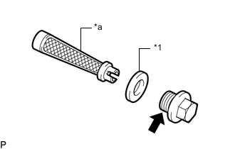
*1 New Gasket *a Mesh Part Adhesive Make sure that the mesh is free from damage and foreign matter.
-
Install 2 new gaskets to 2 new oil control valve filters.
-
Install the 2 oil control filters into the 2 new unions.
-
Apply adhesive to 2 or 3 threads of the unions.
Adhesive Toyota Genuine Adhesive 1344, Three Bond 1344 or equivalent -
Install the 2 unions to the cylinder head sub-assembly and cylinder head LH.
- Torque:
- 62 N*m { 632 kgf*cm, 46 ft.*lbf }
-
-
INSTALL CAMSHAFT TIMING OIL CONTROL VALVE ASSEMBLY (for Bank 2)
-
INSTALL CAMSHAFT TIMING OIL CONTROL VALVE ASSEMBLY (for Bank 1)
-
INSTALL CRANKSHAFT POSITION SENSOR
-
INSTALL VVT SENSOR (for Bank 2)
-
INSTALL VVT SENSOR (for Bank 1)
-
INSTALL CYLINDER BLOCK WATER DRAIN COCK SUB-ASSEMBLY
-
Remove any oil from the threads of the cylinder block water drain cock sub-assembly.
-
Apply adhesive to 2 or 3 threads at the end of the cylinder block water drain cock sub-assembly.
Adhesive Toyota Genuine Adhesive 1324, Three Bond 1324 or equivalent -
Install the cylinder block water drain cock sub-assembly.
- Torque:
- 25 N*m { 255 kgf*cm, 18 ft.*lbf }
Note
-
Install the cylinder block water drain cock sub-assembly within 3 minutes after applying adhesive.
-
Do not expose the cylinder block water drain cock sub-assembly to engine coolant within 1 hour after installation.
-
Rotate the cylinder block water drain cock sub-assembly clockwise as shown in the illustration.
Note
-
Do not rotate the cylinder block water drain cock sub-assembly by more than 1 revolution (360°) after tightening the cylinder block water drain cock sub-assembly to the specified torque.
-
Do not loosen the cylinder block water drain cock sub-assembly after setting it correctly.
-
-
Install the cylinder block water drain cock plug to the cylinder block water drain cock sub-assembly.
- Torque:
- 12.7 N*m { 130 kgf*cm, 9 ft.*lbf }
-
-
INSTALL ENGINE COOLANT TEMPERATURE SENSOR
-
INSTALL ENGINE OIL PRESSURE SWITCH ASSEMBLY