БЛОК ДВИГАТЕЛЯ ПРОВЕРКА

PROCEDURE
-
INSPECT CYLINDER HEAD SET BOLT
-
Check the cylinder head set bolt for damage or deformation.
Tech Tips
If there is any deformation, replace the cylinder head set bolt.
-
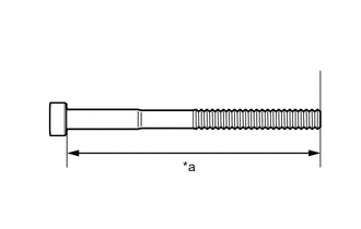
*a Measurement Length Using a vernier caliper, measure the length of the cylinder head set bolt from the seat to the end.
Standard length 141.3 to 142.7 mm (5.56 to 5.62 in.) Maximum length 143.7 mm (5.66 in.) If the length is more than the maximum, replace the cylinder head set bolt. Failure to do so may lead to engine damage.
-
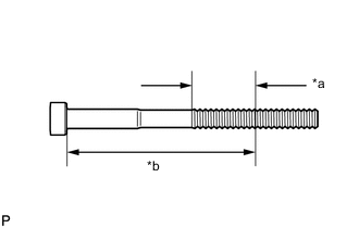
*a Measuring Area *b 76 mm (2.99 in.) Using a vernier caliper, measure the minimum diameter of the elongated thread in the measuring area.
Standard outside diameter 10.85 to 11.0 mm (0.427 to 0.433 in.) Minimum outside diameter 10.7 mm (0.421 in.) Tech Tips
Measure at several points within the measuring area.
If the diameter is less than the minimum, replace the cylinder head set bolt. Failure to do so may lead to engine damage.
-
-
INSPECT CAMSHAFT
-
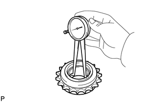
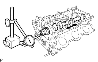
Inspect the camshaft runout.
-
Place the camshaft on V-blocks.
-
Using a dial indicator, measure the runout at the center journal.
Maximum runout 0.06 mm (0.00236 in.) If the runout is more than the maximum, replace the camshaft.
-
-
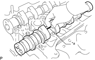
Inspect the cam lobes.
-
Using a micrometer, measure the cam lobe height.
Standard Cam Lobe Height Item Specified Condition Intake side 44.168 to 44.268 mm (1.739 to 1.743 in.) Exhaust side 44.580 to 44.680 mm (1.755 to 1.759 in.) Minimum Cam Lobe Height Item Specified Condition Intake side 44.018 mm (1.73 in.) Exhaust side 44.430 mm (1.75 in.) If the cam lobe height is less than the minimum, replace the camshaft.
-
-
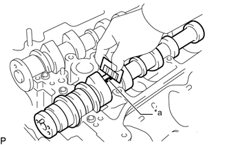
Inspect the camshaft journals.
-
Using a micrometer, measure the journal diameter.
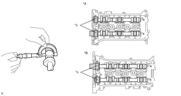
*A for Bank 1 *B for Bank 2 *a Intake Side *b Exhaust Side *c No. 1 Camshaft Journal - - Standard Journal Diameter Item Specified Condition No. 1 journal 35.971 to 35.985 mm (1.416 to 1.417 in.) Other journals 22.959 to 22.975 mm (0.904 to 0.905 in.) If the journal diameter is not as specified, check the camshaft oil clearance.
-
-
-
INSPECT CAMSHAFT TIMING GEAR ASSEMBLY
-
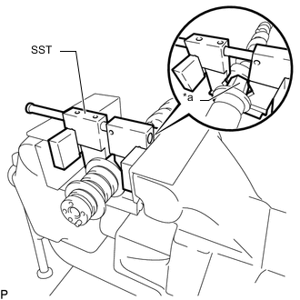
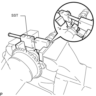
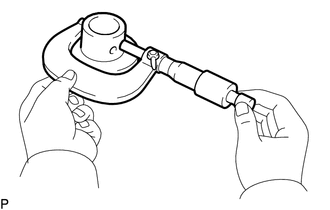
*a Hexagonal Portion Using SST, grip the hexagonal portion, and then secure SST and camshaft in a vise as shown in the illustration.
- SST
- 09212-31010
Note
-
Do not damage the camshaft.
-
Never grip areas other than the hexagonal portion, as this may cause damage.
-
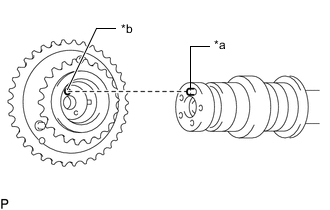
*a Knock Pin *b Knock Pin Hole Align the knock pin hole in the camshaft timing gear assembly with the knock pin of the camshaft and install the camshaft timing gear assembly with the bolt.
- Torque:
- 100 N*m { 1020 kgf*cm, 74 ft.*lbf }
-
Confirm the camshaft timing gear assembly is locked.
-
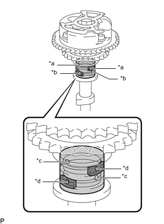
*a Retard Side Paths *b Advance Side Paths *c Open *d Close 
Rubber Piece 
Vinyl Tape Release the lock pin.
-
Clean the camshaft journal with non-residue solvent.
-
Cover the 4 oil paths of the cam journal with vinyl tape as shown in the illustration.
Tech Tips
One of the 2 grooves on the cam journal is for retard side paths (upper) and the other is for advance side paths (lower). Each groove has 2 oil paths. Plug one of the oil paths for each groove with rubber pieces as shown in the illustration before wrapping the cam journal with tape.
-
Prick a hole in the tape at the location of the 2 oil holes not plugged with rubber pieces.
-
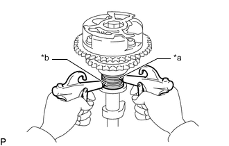
*a Retard Side Paths *b Advance Side Paths Apply approximately 200 kPa (2.0 kgf/cm2, 29 psi) of air pressure to the two broken paths (the advance side path and the retard side path).
Note
Cover the paths with a cloth to avoid oil splashing.
-
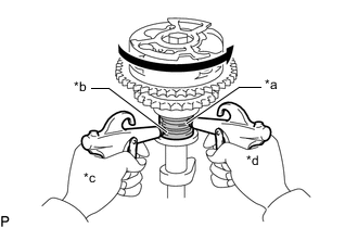
*a Retard Side Paths *b Advance Side Paths *c Hold Pressure *d Decompress Confirm that the camshaft timing gear assembly rotates in the advance direction when reducing the air pressure applied to the retard path.
Tech Tips
When the lock pin is released, the camshaft timing gear assembly rotates in the advance direction.
-
When the camshaft timing gear assembly comes to the most advanced position, release the air pressure from the retard side path, and then release the air pressure from the advance side path.
Note
The camshaft timing gear occasionally shifts to the retard side abruptly if the compressed air applied to the advanced side path is released first. This often results in breakage of the lock pin.
-
-
Check for smooth rotation.
-
Turn the camshaft timing gear assembly within its movable range (30 to 31°) 2 or 3 times, but do not turn it to the most retarded position. Make sure that the gear turns smoothly.
Note
Be sure to perform this check by hand, instead of with air pressure.
Tech Tips
Do not allow the camshaft timing gear assembly to lock.
If it locks, release the lock pin again.
-
-
Check the lock in the most retarded position.
-
Confirm that the camshaft timing gear assembly is locked at the most retarded position.
-
-
*a Hexagonal Portion Using SST, grip the hexagonal portion, and then secure SST and camshaft in a vise as shown in the illustration.
- SST
- 09212-31010
Note
-
Do not damage the camshaft.
-
Never grip areas other than the hexagonal portion, as this may cause damage.
-
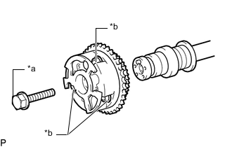
*a Bolt *b Do Not Remove Remove the bolt and camshaft timing gear assembly.
Note
Do not remove the other 3 bolts.
-
-
INSPECT CHAIN SUB-ASSEMBLY
-
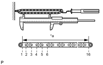
*a Measuring Area Using a spring scale, pull the chain sub-assembly with a force of 147 N (15 kgf, 33 lbf) and measure the length of the chain sub-assembly by using a vernier caliper.
Maximum chain elongation 146.8 mm (5.78 in.) Tech Tips
Perform the measurement at 3 random places.
If a measurement is more than the maximum, replace the chain sub-assembly.
-
-
INSPECT NO. 2 CHAIN SUB-ASSEMBLY
-
Using a spring scale, pull the No. 2 chain sub-assembly with a force of 147 N (15 kgf, 33 lbf) and measure the length of the No. 2 chain sub-assembly by using a vernier caliper.
Maximum chain elongation 146.8 mm (5.78 in.) Tech Tips
Perform the measurement at 3 random places.
If a measurement is more than the maximum, replace the No. 2 chain sub-assembly.
-
-
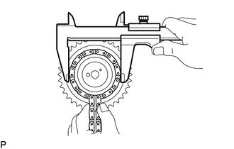
INSPECT CAMSHAFT TIMING GEAR ASSEMBLY
-
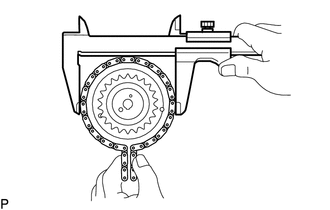
Wrap the chain sub-assembly around the camshaft timing gear assembly.
-
Using a vernier caliper, measure the camshaft timing gear assembly together with the chain sub-assembly.
Minimum gear diameter (with chain) 115.5 mm (4.55 in.) Tech Tips
The vernier caliper must contact the chain rollers for the measurement.
If the diameter is less than the minimum, replace the chain sub-assembly and camshaft timing gear assembly.
-
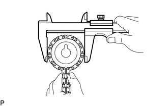
Wrap the No. 2 chain sub-assembly around the camshaft timing gear assembly.
-
Using a vernier caliper, measure the camshaft timing gear assembly together with the No. 2 chain sub-assembly.
Minimum gear diameter (with No. 2 chain) 73.1 mm (2.88 in.) Tech Tips
The vernier caliper must contact the chain rollers for the measurement.
If the diameter is less than the minimum, replace the No. 2 chain sub-assembly and camshaft timing gear assembly.
-
-
INSPECT CAMSHAFT TIMING SPROCKET
-
Wrap the No. 2 chain sub-assembly around the camshaft timing sprocket.
-
Using a vernier caliper, measure the camshaft timing sprocket diameter together with the No. 2 chain sub-assembly.
Minimum gear diameter (with No. 2 chain) 73.1 mm (2.88 in.) Tech Tips
The vernier caliper must contact the chain rollers for the measurement.
If the diameter is less than the minimum, replace the No. 2 chain sub-assembly and camshaft timing sprocket.
-
-
INSPECT CRANKSHAFT TIMING SPROCKET
-
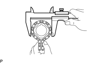
Wrap the chain sub-assembly around the crankshaft timing sprocket.
-
Using a vernier caliper, measure the crankshaft timing sprocket diameter together with the chain sub-assembly.
Minimum gear diameter (with chain) 61.0 mm (2.40 in.) Tech Tips
The vernier caliper must contact the chain rollers for the measurement.
If the diameter is less than the minimum, replace the chain sub-assembly and crankshaft timing sprocket.
-
-
INSPECT IDLE SPROCKET ASSEMBLY
-
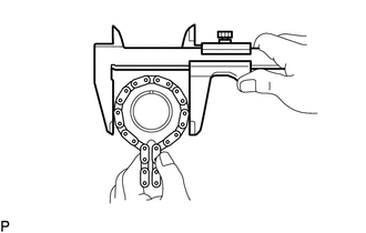
Wrap the chain sub-assembly around the idle sprocket assembly.
-
Using a vernier caliper, measure the idle sprocket assembly together with the chain sub-assembly.
Minimum gear diameter (with chain) 61.0 mm (2.40 in.) Tech Tips
The vernier caliper must contact the chain rollers for the measurement.
If the diameter is less than the minimum, replace the chain sub-assembly and idle sprocket assembly.
-
-
INSPECT IDLE SPROCKET OIL CLEARANCE
-
Using a micrometer, measure the No. 1 idle gear shaft diameter.
Standard idle gear shaft diameter 22.987 to 23.000 mm (0.905 to 0.906 in.) -
Using a caliper gauge, measure the inside diameter of the idle sprocket assembly.
Standard idle sprocket inside diameter 23.02 to 23.03 mm (0.906 to 0.907 in.) -
Subtract the No. 1 idle gear shaft diameter measurement from the idle sprocket assembly inside diameter measurement.
Standard oil clearance 0.020 to 0.043 mm (0.000787 to 0.00169 in.) Maximum oil clearance 0.093 mm (0.00366 in.) If the oil clearance is more than the maximum, replace the No. 1 idle gear shaft and idle sprocket assembly.
-
-
INSPECT NO. 1 CHAIN TENSIONER ASSEMBLY
-
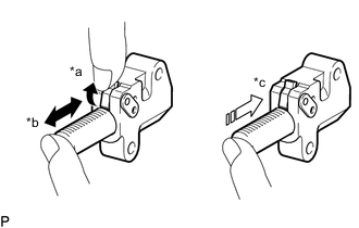
*a Raise *b Move *c Lock Move the stopper plate upward to release the lock. Push the plunger and check that it moves smoothly.
If necessary, replace the No. 1 chain tensioner assembly.
-
-
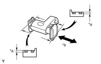
INSPECT NO. 2 CHAIN TENSIONER ASSEMBLY
-
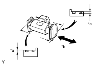
*a Depth *b Moves Smoothly Check that the plunger moves smoothly.
-
Measure the depth of wear of the No. 2 chain tensioner.
Maximum depth 1.0 mm (0.0394 in.) If the depth is more than the maximum, replace the No. 2 chain tensioner assembly.
-
-
INSPECT NO. 3 CHAIN TENSIONER ASSEMBLY
-
*a Depth *b Moves Smoothly Check that the plunger moves smoothly.
-
Measure the depth of wear of the No. 3 chain tensioner.
Maximum depth 1.0 mm (0.0394 in.) If the depth is more than the maximum, replace the No. 3 chain tensioner assembly.
-
-
INSPECT CHAIN TENSIONER SLIPPER
-
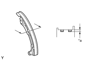
*a Depth Measure the worn depth of the chain tensioner slipper.
Maximum depth 1.0 mm (0.0394 in.) If the depth is more than the maximum, replace the chain tensioner slipper.
-
-
INSPECT NO. 1 CHAIN VIBRATION DAMPER
-
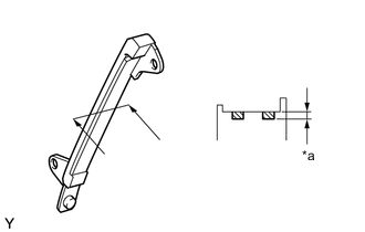
*a Depth Measure the worn depth of the No. 1 chain vibration damper.
Maximum depth 1.0 mm (0.0394 in.) If the depth is more than the maximum, replace the No. 1 chain vibration damper.
-
-
INSPECT NO. 2 CHAIN VIBRATION DAMPER
-
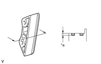
*a Depth Measure the worn depth of the No. 2 chain vibration damper.
Maximum depth 1.0 mm (0.0394 in.) If the depth is more than the maximum, replace the No. 2 chain vibration damper.
-
-
INSPECT CAMSHAFT THRUST CLEARANCE
-
for Bank 1:
-
Install the No. 1 camshaft bearing.
-
Install the No. 2 camshaft bearing.
-
Place the camshaft and No. 2 camshaft to the cylinder head sub-assembly.
-
Install the camshaft bearing cap.
-
Using a dial indicator, measure the camshaft thrust clearance while moving the camshaft back and forth.
Standard Camshaft Thrust Clearance Item Specified Condition Intake side 0.04 to 0.09 mm (0.00157 to 0.00354 in.) Exhaust side 0.08 to 0.13 mm (0.00315 to 0.00512 in.) Maximum Camshaft Thrust Clearance Item Specified Condition Intake side 0.11 mm (0.00433 in.) Exhaust side 0.15 mm (0.00591 in.) If the thrust clearance is more than the maximum, replace the camshafts.
If necessary, replace the camshaft bearing caps and cylinder head sub-assembly as a set.
-
-
for Bank 2:
-
Place the No. 3 camshaft sub-assembly and No. 4 camshaft sub-assembly to the cylinder head LH.
-
Install the camshaft bearing cap.
-
Using a dial indicator, measure the thrust clearance while moving the camshaft back and forth.
Standard Camshaft Thrust Clearance Item Specified Condition Intake side 0.05 to 0.10 mm (0.00197 to 0.00394 in.) Exhaust side 0.08 to 0.13 mm (0.00315 to 0.00512 in.) Maximum Camshaft Thrust Clearance Item Specified Condition Intake side 0.12 mm (0.00472 in.) Exhaust side 0.15 mm (0.00591 in.) If the thrust clearance is more than the maximum, replace the camshafts.
If necessary, replace the camshaft bearing caps and cylinder head LH as a set.
-
-
-
INSPECT CAMSHAFT OIL CLEARANCE
-
for Bank 1:
-
Clean the camshaft bearing caps, camshaft bearings and camshaft journals.
-
Check the bearings for flaking and scoring.
If the bearings are damaged, replace the cylinder head sub-assembly.
-
Install the No. 1 camshaft bearing.
-
Install the No. 2 camshaft bearing.
-
Place the camshaft and No. 2 camshaft on the cylinder head sub-assembly.
Note
Do not turn the camshaft and No. 2 camshaft.
-
*a Plastigage Lay a strip of Plastigage across each of the camshaft journals.
-
Install the camshaft bearing caps.
-
Remove the camshaft bearing caps.
-
*a Plastigage Measure the Plastigage at its widest point.
Standard Camshaft Oil Clearance Item Specified Condition No. 1 journal (intake side) 0.028 to 0.048 mm (0.00110 to 0.00189 in.) No. 1 journal (exhaust side) 0.040 to 0.079 mm (0.00157 to 0.00311 in.) Others 0.025 to 0.062 mm (0.000984 to 0.00244 in.) Maximum Camshaft Oil Clearance Item Specified Condition No. 1 journal (intake side) 0.07 mm (0.00276 in.) Others 0.10 mm (0.00394 in.) If the oil clearance is more than the maximum, replace the camshaft bearings and/or camshaft.
If necessary, replace the camshaft bearing caps and cylinder head together.
Standard (Reference) Item Specified Condition Cylinder head journal bore diameter 40.009 to 40.019 mm (1.5752 to 1.5755 in.) No. 1 Camshaft bearing center wall thickness 2.004 to 2.008 mm (0.0789 to 0.0791 in.) No. 2 Camshaft bearing center wall thickness 2.000 to 2.012 mm (0.0787 to 0.0792 in.) Camshaft journal diameter 35.971 to 35.985 mm (1.4162 to 1.4167 in.)
-
-
for Bank 2:
-
Clean the camshaft bearing caps, camshaft bearings and camshaft journals.
-
Check the bearings for flaking and scoring.
If the bearings are damaged, replace the cylinder head LH.
-
Place the No. 3 camshaft sub-assembly and No. 4 camshaft sub-assembly on the cylinder head LH.
Note
Do not turn the No. 3 camshaft sub-assembly and No. 4 camshaft sub-assembly.
-
Lay a strip of Plastigage across each of the camshaft journals.
-
Install the camshaft bearing caps.
-
Remove the camshaft bearing caps.
-
Measure the Plastigage at its widest point.
Standard Camshaft Oil Clearance Item Specified Condition No. 1 journal (intake side) 0.050 to 0.089 mm (0.00197 to 0.00350 in.) No. 1 journal (exhaust side) 0.040 to 0.079 mm (0.00157 to 0.00311 in.) Others 0.025 to 0.062 mm (0.000984 to 0.00244 in.) Maximum Camshaft Oil Clearance Item Specified Condition No. 1 journal (intake side) 0.08 mm (0.00315 in.) Others 0.10 mm (0.00394 in.) If the oil clearance is more than the maximum, replace the camshaft bearings and/or camshaft.
If necessary, replace the camshaft bearing caps and cylinder head LH together.
Standard (Reference) Item Specified Condition Cylinder head journal bore diameter 40.009 to 40.019 mm (1.5752 to 1.5755 in.) Camshaft journal diameter 35.971 to 35.985 mm (1.4162 to 1.4167 in.)
-
-
-
INSPECT EXHAUST MANIFOLD FOR FLATNESS
-
Using a precision straightedge and feeler gauge, measure the warpage of the contact surface of the cylinder head.
Maximum warpage 0.70 mm (0.0276 in.) If the warpage is more than the maximum, replace the exhaust manifold.
-
-
INSPECT INTAKE MANIFOLD FOR FLATNESS
-
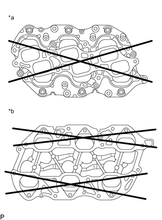
*a Intake Air Surge Tank Side *b Cylinder Head Side Using a precision straightedge and feeler gauge, measure the warpage of the contact surface of the cylinder head and intake air surge tank.
Maximum Warpage Item Specified Condition Intake air surge tank side 0.80 mm (0.0315 in.) Cylinder head side 0.20 mm (0.00787 in.) If the warpage is more than the maximum, replace the intake manifold.
-