ЗАЗОР В ПРИВОДЕ КЛАПАНОВ РЕГУЛИРОВКА
PROCEDURE
-
REMOVE INTAKE AIR SURGE TANK
-
REMOVE SPARK PLUG
-
REMOVE CYLINDER HEAD COVER SUB-ASSEMBLY
-
REMOVE CYLINDER HEAD COVER SUB-ASSEMBLY LH
-
SET NO. 1 CYLINDER TO TDC/COMPRESSION
-
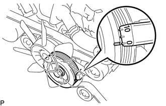
Turn the crankshaft pulley and align its groove with the "0" timing mark of the timing chain cover sub-assembly.
-
Check that the timing marks of the camshaft timing gears are aligned with the timing marks of the bearing cap as shown in the illustration.
If not, turn the crankshaft 1 complete revolution (360°) and align the timing marks as above.
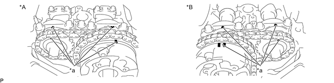
*A for Bank 1 *B for Bank 2 *a Timing Mark - -
-
-
INSPECT VALVE CLEARANCE
-
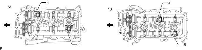
Using a feeler gauge, measure the valve clearance indicated in the illustration.
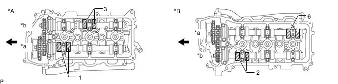
*A for Bank 1 *B for Bank 2 *a Intake Side *b Exhaust Side 
Engine Front Side - - Standard Valve Clearance (Cold) Item Specified Condition Intake Side 0.15 to 0.25 mm (0.00591 to 0.00984 in.) Exhaust Side 0.29 to 0.39 mm (0.0114 to 0.0154 in.) Record the out-of-specification valve clearance measurements. They will be used later to determine the required replacement valve lifter.
-
Turn the crankshaft 2/3 of a revolution (240°).
-
Using a feeler gauge, measure the valve clearance indicated in the illustration.
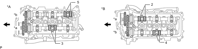
*A for Bank 1 *B for Bank 2 *a Intake Side *b Exhaust Side Engine Front Side - - Standard Valve Clearance (Cold) Item Specified Condition Intake Side 0.15 to 0.25 mm (0.00591 to 0.00984 in.) Exhaust Side 0.29 to 0.39 mm (0.0114 to 0.0154 in.) Record the out-of-specification valve clearance measurements. They will be used later to determine the required replacement valve lifter.
-
Turn the crankshaft 2/3 of a revolution (240°).
-
Using a feeler gauge, measure the valve clearance indicated in the illustration.
*A for Bank 1 *B for Bank 2 *a Intake Side *b Exhaust Side Engine Front Side - - Standard Valve Clearance (Cold) Item Specified Condition Intake Side 0.15 to 0.25 mm (0.00591 to 0.00984 in.) Exhaust Side 0.29 to 0.39 mm (0.0114 to 0.0154 in.) Record the out-of-specification valve clearance measurements. They will be used later to determine the required replacement valve lifter.
-
-
ADJUST VALVE CLEARANCE
-
Remove the camshafts.
-
Remove the 24 valve lifters from the cylinder head LH and RH.
-
Determine the size of the valve lifter to be installed according to the following formulas and charts.
-
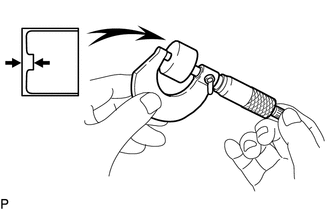
Using a micrometer, measure the thickness of the removed valve lifter.
-
Calculate the thickness of a new valve lifter so that the valve clearance comes within the specified range.
T Thickness of removed valve lifter A Measured valve clearance N Thickness of new valve lifter Intake N = T + (A - 0.20 mm (0.00787 in.)) Exhaust N = T + (A - 0.34 mm (0.0134 in.)) -
Select a new valve lifter with a thickness as close as possible to the calculated value.
Tech Tips
Lifters are available in 35 sizes in increments of 0.020 mm (0.000787 in.), from 5.060 mm (0.1992 in.) to 5.740 mm (0.2260 in.).
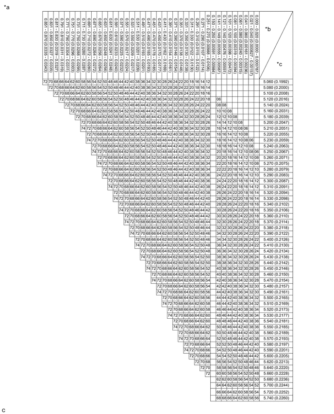
*a Valve Lifter Selection Chart (Intake) *b Measured Clearance mm (in.) *c Installed Lifter Thickness mm (in.) - - Intake valve clearance (Cold) 0.15 to 0.25 mm (0.00591 to 0.00984 in.) EXAMPLE:
A 5.250 mm (0.2067 in.) lifter is installed and the measured clearance is 0.400 mm (0.0157 in.). Replace the 5.250 mm (0.2067 in.) lifter with a No. 46 lifter.
New Lifter Thickness Lifter No. Thickness Lifter No. Thickness Lifter No. Thickness 06 5.060 mm (0.1992 in.) 30 5.300 mm (0.2087 in.) 54 5.540 mm (0.2181 in.) 08 5.080 mm (0.2000 in.) 32 5.320 mm (0.2094 in.) 56 5.560 mm (0.2189 in.) 10 5.100 mm (0.2008 in.) 34 5.340 mm (0.2102 in.) 58 5.580 mm (0.2197 in.) 12 5.120 mm (0.2016 in.) 36 5.360 mm (0.2110 in.) 60 5.600 mm (0.2205 in.) 14 5.140 mm (0.2024 in.) 38 5.380 mm (0.2118 in.) 62 5.620 mm (0.2213 in.) 16 5.160 mm (0.2031 in.) 40 5.400 mm (0.2126 in.) 64 5.640 mm (0.2220 in.) 18 5.180 mm (0.2039 in.) 42 5.420 mm (0.2134 in.) 66 5.660 mm (0.2228 in.) 20 5.200 mm (0.2047 in.) 44 5.440 mm (0.2142 in.) 68 5.680 mm (0.2236 in.) 22 5.220 mm (0.2055 in.) 46 5.460 mm (0.2150 in.) 70 5.700 mm (0.2244 in.) 24 5.240 mm (0.2063 in.) 48 5.480 mm (0.2157 in.) 72 5.720 mm (0.2252 in.) 26 5.260 mm (0.2071 in.) 50 5.500 mm (0.2165 in.) 74 5.740 mm (0.2260 in.) 28 5.280 mm (0.2079 in.) 52 5.520 mm (0.2173 in.) - - 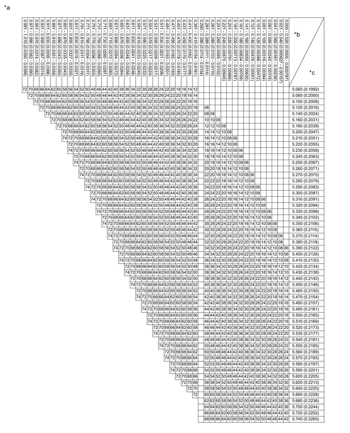
*a Valve Lifter Selection Chart (Exhaust) *b Measured Clearance mm (in.) *c Installed Lifter Thickness mm (in.) - - Exhaust valve clearance (Cold) 0.29 to 0.39 mm (0.0114 to 0.0154 in.) EXAMPLE:
A 5.340 mm (0.2102 in.) lifter is installed and the measured clearance is 0.480 mm (0.0189 in.). Replace the 5.340 mm (0.2102 in.) lifter with a No. 48 lifter.
New Lifter Thickness Lifter No. Thickness Lifter No. Thickness Lifter No. Thickness 06 5.060 mm (0.1992 in.) 30 5.300 mm (0.2087 in.) 54 5.540 mm (0.2181 in.) 08 5.080 mm (0.2000 in.) 32 5.320 mm (0.2094 in.) 56 5.560 mm (0.2189 in.) 10 5.100 mm (0.2008 in.) 34 5.340 mm (0.2102 in.) 58 5.580 mm (0.2197 in.) 12 5.120 mm (0.2016 in.) 36 5.360 mm (0.2110 in.) 60 5.600 mm (0.2205 in.) 14 5.140 mm (0.2024 in.) 38 5.380 mm (0.2118 in.) 62 5.620 mm (0.2213 in.) 16 5.160 mm (0.2031 in.) 40 5.400 mm (0.2126 in.) 64 5.640 mm (0.2220 in.) 18 5.180 mm (0.2039 in.) 42 5.420 mm (0.2134 in.) 66 5.660 mm (0.2228 in.) 20 5.200 mm (0.2047 in.) 44 5.440 mm (0.2142 in.) 68 5.680 mm (0.2236 in.) 22 5.220 mm (0.2051 in.) 46 5.460 mm (0.2150 in.) 70 5.700 mm (0.2244 in.) 24 5.240 mm (0.2063 in.) 48 5.480 mm (0.2157 in.) 72 5.720 mm (0.2252 in.) 26 5.260 mm (0.2071 in.) 50 5.500 mm (0.2165 in.) 74 5.740 mm (0.2260 in.) 28 5.280 mm (0.2079 in.) 52 5.520 mm (0.2173 in.) - -
-
-
Install the camshafts.
-
Check the valve clearance.
If the result is not as specified, adjust the valve clearance.
-
-
INSTALL CYLINDER HEAD COVER SUB-ASSEMBLY LH
-
INSTALL CYLINDER HEAD COVER SUB-ASSEMBLY
-
INSTALL SPARK PLUG
-
INSTALL INTAKE AIR SURGE TANK
-
INSPECT IGNITION TIMING