ПРОКЛАДКА ГОЛОВКИ БЛОКА ЦИЛИНДРОВ СНЯТИЕ
CAUTION / NOTICE / HINT
The necessary procedures (adjustment, calibration, initialization, or registration) that must be performed after parts are removed, installed, or replaced during the cylinder head gasket removal/installation are shown below.
| Replacement Part or Procedure | Necessary Procedures | Effects/Inoperative when not Performed | Link |
|---|---|---|---|
| Replacement of ECM | Vehicle Identification Number (VIN) registration | DTC P0630 is output | |
| Code registration (Immobiliser system) | Engine start function | See the Service Bulletin for the registration method. | |
| Replacement of engine assembly | Inspection after repair | Poor idle, engine start, etc. | |
|
Inspection After Repair | Poor idle, engine start, etc. |
PROCEDURE
-
REMOVE TIMING CHAIN COVER SUB-ASSEMBLY
-
REMOVE REAR WATER BY-PASS JOINT
-
SET NO. 1 CYLINDER TO TDC/COMPRESSION
-
REMOVE NO. 1 CHAIN TENSIONER ASSEMBLY
-
REMOVE CHAIN TENSIONER SLIPPER
-
REMOVE IDLE SPROCKET ASSEMBLY
-
REMOVE NO. 2 CHAIN VIBRATION DAMPER
-
REMOVE CHAIN SUB-ASSEMBLY
-
REMOVE NO. 1 CHAIN VIBRATION DAMPER
-
REMOVE CAMSHAFT TIMING GEARS AND NO. 2 CHAIN SUB-ASSEMBLY (for Bank 1)
-
REMOVE NO. 2 CHAIN TENSIONER ASSEMBLY
-
REMOVE CAMSHAFT TIMING GEARS AND NO. 2 CHAIN SUB-ASSEMBLY (for Bank 2)
-
REMOVE NO. 3 CHAIN TENSIONER ASSEMBLY
-
REMOVE CAMSHAFT BEARING CAP (for Bank 1)
-
REMOVE CAMSHAFT
-
REMOVE NO. 2 CAMSHAFT
-
REMOVE NO. 1 CAMSHAFT BEARING
-
REMOVE NO. 2 CAMSHAFT BEARING
-
REMOVE CAMSHAFT BEARING CAP (for Bank 2)
-
REMOVE NO. 3 CAMSHAFT SUB-ASSEMBLY
-
REMOVE NO. 4 CAMSHAFT SUB-ASSEMBLY
-
REMOVE CYLINDER HEAD SUB-ASSEMBLY
-
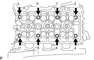
Using a 10 mm bi-hexagon wrench, uniformly loosen the 8 cylinder head set bolts in the sequence shown in the illustration and remove the 8 cylinder head set bolts and 8 plate washers.
Note
-
Be careful not to drop the plate washers into the cylinder head sub-assembly.
-
Cylinder head sub-assembly warpage or cracking could result from removing bolts in the incorrect order.
Tech Tips
Be sure to keep the removed parts separate for each installation position.
-
-
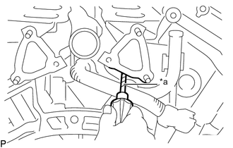
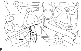
*a Protective Tape Remove the cylinder head sub-assembly.
Note
Be careful not to damage the contact surfaces of the cylinder head sub-assembly and cylinder block sub-assembly.
Tech Tips
-
If the cylinder head sub-assembly is difficult to lift off, pry between the cylinder head sub-assembly and cylinder block sub-assembly with a screwdriver.
-
Tape the screwdriver tip before use.
-
-
-
REMOVE CYLINDER HEAD GASKET
-
REMOVE CYLINDER HEAD LH
-
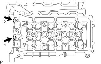
Uniformly loosen the 2 bolts in the sequence shown in the illustration and remove the 2 bolts.
-
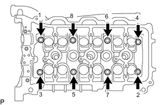
Using a 10 mm bi-hexagon wrench, uniformly loosen the 8 cylinder head set bolts in the sequence shown in the illustration and remove the 8 cylinder head set bolts and 8 plate washers.
Note
-
Be careful not to drop the plate washers into the cylinder head LH.
-
Cylinder head LH warpage or cracking could result from removing bolts in the incorrect order.
Tech Tips
Be sure to keep the removed parts separate for each installation position.
-
-
*a Protective Tape Remove the cylinder head LH.
Note
Be careful not to damage the contact surfaces of the cylinder head LH and cylinder block sub-assembly.
Tech Tips
-
If the cylinder head LH is difficult to lift off, pry between the cylinder head LH and cylinder block sub-assembly with a screwdriver.
-
Tape the screwdriver tip before use.
-
-
-
REMOVE NO. 2 CYLINDER HEAD GASKET
-
INSPECT CYLINDER HEAD SET BOLT
-
INSPECT CYLINDER HEAD SUB-ASSEMBLY