СИСТЕМА ECD, Diagnostic DTC:P00AF
| DTC Code | DTC Name |
|---|---|
| P00AF | Turbocharger/Supercharger Boost Control "A" Module Performance |
DESCRIPTION
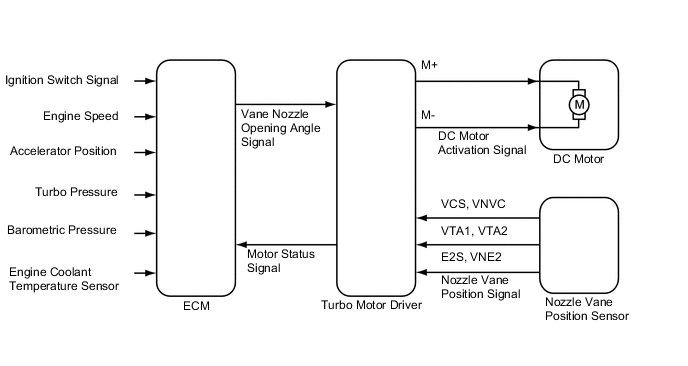
The turbocharger system is comprised of the Variable Nozzle (VN) type turbocharger, the turbo motor driver and ECM.
The turbocharger has a nozzle vane which opens and closes to control the volume of the exhaust gas flowing into the turbine. This, in turn, controls the boost pressure, when the nozzle vane moves towards the closing direction, the pressure increases. When the vane moves towards the opening direction, the pressure decreases.
The turbocharger actuator, which consists of the DC motor and the nozzle vane position sensor, is built on the turbocharger sub-assembly, and activates the nozzle vane. The nozzle vane position sensor detects the opening angle of the nozzle vane. The turbo motor driver receives an opening angle request from the ECM and a nozzle vane position signal from the nozzle vane position sensor. Based on these signals, the turbo motor driver operates the DC motor and adjusts the nozzle vane opening angle. The turbo motor driver sends the status as a turbo driver status signal to the ECM
The ECM sends a target nozzle vane position signal to the turbo motor driver to obtain the nozzle vane position for the optimal boost pressure in accordance with the driving conditions.
| DTC No. | Detection Item | DTC Detection Condition | Trouble Area | MIL | Memory |
|---|---|---|---|---|---|
| P00AF | Turbocharger/Supercharger Boost Control "A" Module Performance | When communication error occurs between turbo motor and ECM (1 trip detection logic) |
|
Comes on | DTC stored |
CONFIRMATION DRIVING PATTERN
| DTC Detection Drive Pattern | Ignition switch to ON for 5 seconds |
WIRING DIAGRAM
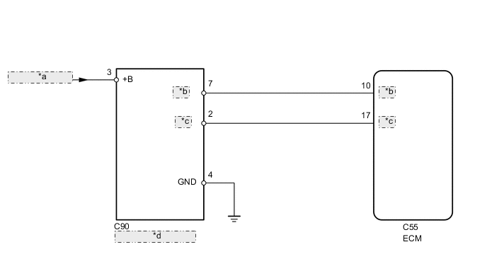
| *a | from FEI-MAIN NO. 1 Relay |
| *b | VNTO |
| *c | VNTI |
| *d | Turbo Motor Driver |
CAUTION / NOTICE / HINT
Note
After replacing the ECM, the new ECM needs registration (See page ) and initialization Click here.
Tech Tips
-
Read freeze frame data using the GTS. Freeze frame data records the engine condition when malfunctions are detected. When troubleshooting, freeze frame data can help determine if the vehicle was moving or stationary, if the engine was warmed up or not, and other data from the time the malfunction occurred.
-
Excessive electrical noise, such as from wireless radios or electrical modifications, may cause a DTC output.
PROCEDURE
-
CHECK TURBO MOTOR DRIVER
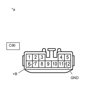
*a Front view of wire harness connector
(to Turbo Motor Driver)
-
Disconnect the turbo motor driver connector.
-
Turn the ignition switch to ON.
-
Measure the voltage according to the value(s) in the table below.
Standard Voltage Tester Connection Condition Specified Condition C90-3 (+B) - C90-4 (GND) Always 11 to 14 V -
Measure the resistance according to the value(s) in the table below.
Standard Resistance Tester Connection Condition Specified Condition C90-4 (GND) - Body ground Always Below 1 Ω -
Reconnect the turbo motor driver connector.
Result Proceed to OK NG
NG 
REPAIR OR REPLACE HARNESS OR CONNECTOR Click here
OK 
-
-
CHECK HARNESS AND CONNECTOR (TURBO MOTOR DRIVER - ECM)
-
Disconnect the ECM connector.
-
Disconnect the turbo motor driver connector.
-
Measure the resistance according to the value(s) in the table below.
Standard Resistance Tester Connection Condition Specified Condition C55-10 (VNTO) - C90-7 (VNTO) Always Below 1 Ω C55-17 (VNTI) - C90-2 (VNTI) Always Below 1 Ω C55-10 (VNTO) or C90-7 (VNTO) - Body ground Always 10 kΩ or higher C55-17 (VNTI) or C90-2 (VNTI) - Body ground Always 10 kΩ or higher -
Reconnect the turbo motor driver connector.
-
Reconnect the ECM connector.
Result Proceed to OK NG
NG
GO TO STEP 5 Click here
OK
-
-
INSPECT ECM (VNTO VOLTAGE)
-
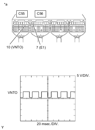
*a Component with harness connected
(ECM)
While idling the engine, check the waveform of the ECM connectors using an oscilloscope.
Standard Voltage Tester Connection Condition Specified Condition C55-10 (VNTO) - C56-7 (E1) Idling Correct waveform is as shown Result Proceed to OK NG
NG
REPLACE ECM Click here
OK
-
-
INSPECT ECM (VNTI VOLTAGE)
-
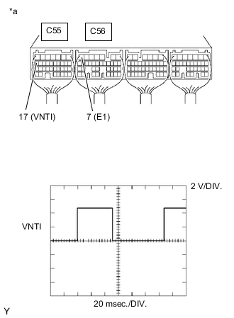
*a Component with harness connected
(ECM)
While idling the engine, check the waveform of the ECM connectors using an oscilloscope.
Standard Voltage Tester Connection Condition Specified Condition C55-17 (VNTI) - C56-7 (E1) Idling Correct waveform is as shown Result Proceed to OK NG
OK 
CHECK FOR INTERMITTENT PROBLEMS Click here
NG
REPLACE TURBO MOTOR DRIVER Click here
-
-
REPAIR OR REPLACE HARNESS OR CONNECTOR
-
Repair or replace the harness or connector.
Result Proceed to NEXT
NEXT
GO TO STEP 8 Click here
-
-
REPLACE ECM
-
Replace the ECM.
Result Proceed to NEXT
NEXT
GO TO STEP 8 Click here
-
-
REPLACE TURBO MOTOR DRIVER
-
Replace turbo motor driver.
Result Proceed to NEXT
NEXT
-
-
CONFIRM WHETHER MALFUNCTION HAS BEEN SUCCESSFULLY REPAIRED
-
Connect the GTS to the DLC3.
-
Turn the ignition switch to ON and turn the GTS on.
-
Clear the DTCs.
Powertrain > Engine > Clear DTCs -
Start the engine.
-
Drive the vehicle with a city driving pattern at least 10 minutes.
-
Enter the following menus: Powertrain / Engine / Trouble Codes.
Powertrain > Engine > Trouble Codes -
Confirm that the DTC is not output again.
Result Proceed to NEXT
NEXT
END
-