РЕЛЕ ПРОВЕРКА БЕЗ СНЯТИЯ С АВТОМОБИЛЯ
PROCEDURE
-
INSPECT INJ RELAY (INJ)
-
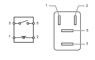
Measure the resistance according to the value(s) in the table below.
Standard Resistance Tester Connection Condition Specified Condition 3 - 5 Battery voltage not applied to terminals 1 and 2 10 kΩ or higher Battery voltage applied to terminals 1 and 2 Below 1 Ω If the result is not as specified, replace the INJ relay.
-
-
INSPECT A/F HTR RELAY
-
Measure the resistance according to the value(s) in the table below.
Standard Resistance Tester Connection Condition Specified Condition 3 - 5 Battery voltage not applied to terminals 1 and 2 10 kΩ or higher Battery voltage applied to terminals 1 and 2 Below 1 Ω If the result is not as specified, replace the A/F HTR relay.
-
-
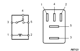
INSPECT FUEL PMP/AIR PMP HTR RELAY
-
Measure the resistance according to the value(s) in the table below.
Standard Resistance Tester Connection Condition Specified Condition 3 - 4 Battery voltage is not applied to terminals 1 and 2 Below 1 Ω Battery voltage is applied to terminals 1 and 2 10 kΩ or higher 3 - 5 Battery voltage is not applied to terminals 1 and 2 10 kΩ or higher Battery voltage is applied to terminals 1 and 2 Below 1 Ω If the result is not as specified, replace the FUEL PMP/AIR PMP HTR relay.
-
-
INSPECT INSTRUMENT PANEL JUNCTION BLOCK ASSEMBLY
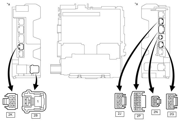
*a Component without harness connected
(Instrument Panel Junction Block Assembly)
- -
-
Remove the instrument panel junction block assembly.
-
Remove the body ECU from the instrument panel junction block assembly.
-
Inspect the EFI MAIN NO. 1 relay.
Note
Before performing the relay inspections for the relays of instrument panel junction block assembly, inspect the EFI-MAIN NO. 1 and EFI NO. 1 fuses.
-
Measure the resistance according to the value(s) in the table below.
Standard Resistance Tester Connection Condition Specified Condition 2B-1 - 2G-5 Battery voltage not applied to terminals 2P-9 and 2J-5 10 kΩ or higher Battery voltage applied to terminals 2P-9 and 2J-5 Below 1 Ω 2B-1 - 2K-3 Battery voltage not applied to terminals 2P-9 and 2J-5 10 kΩ or higher Battery voltage applied to terminals 2P-9 and 2J-5 Below 1 Ω 2B-1 - 2K-4 Battery voltage not applied to terminals 2P-9 and 2J-5 10 kΩ or higher Battery voltage applied to terminals 2P-9 and 2J-5 Below 1 Ω 2B-1 - 2N-1 Battery voltage not applied to terminals 2P-9 and 2J-5 10 kΩ or higher Battery voltage applied to terminals 2P-9 and 2J-5 Below 1 Ω If the result is not as specified, replace the instrument panel junction block assembly.
-
-
Inspect the C/OPN NO. 1 relay.
Note
Before performing the relay inspections for the relays of instrument panel junction block assembly, inspect the EFI-MAIN NO. 1 and IG2 NO. 1 fuses and EFI-MAIN NO. 1 relay.
-
Measure the resistance according to the value(s) in the table below.
Standard Resistance Tester Connection Condition Specified Condition 2B-1 - 2K-5 Battery voltage applied to terminals 2P-9 and 2J-5 and battery voltage not applied to terminals 2G-1 and 2P-8 10 kΩ or higher Battery voltage applied to terminals 2P-9 and 2J-5, and 2G-1 and 2P-8 Below 1 Ω If the result is not as specified, replace the instrument panel junction block assembly.
-
-
Install the body ECU to the instrument panel junction block assembly.
-
Install the instrument panel junction block assembly.
-