FRONT BUMPER(for VELLFIRE) REMOVAL
CAUTION / NOTICE / HINT
The necessary procedures (adjustment, calibration, initialization or registration) that must be performed after parts are removed, installed or replaced during the front bumper cover installation/removal are shown below.
| Replacement Part or Procedure | Necessary Procedures | Effects/Inoperative Functions when not Performed | Link |
|---|---|---|---|
| Removal/installation of the Front television camera assembly or radiator grille assembly | Television camera view adjustment | Panoramic view monitor system | Click here for Initialization Click here for Calibration |
PROCEDURE
-
REMOVE RADIATOR COVER SUB-ASSEMBLY
-
REMOVE RADIATOR GRILLE
-
REMOVE LOWER RADIATOR GRILLE BRACKET LH
-

Remove in this Direction Detach the claw and remove the lower radiator grille bracket LH.
-
-
REMOVE LOWER RADIATOR GRILLE BRACKET RH
Tech Tips
Use the same procedure described for the LH side.
-
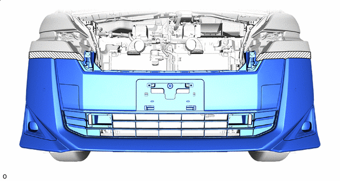
REMOVE FRONT BUMPER COVER
-
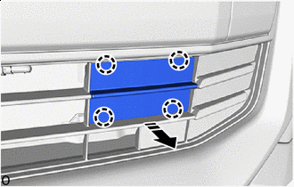
*a 90° Rotation Direction Using a screwdriver, turn the pin hold clip 90° and remove the 2 pin hold clips.
Tech Tips
Use the same procedure for the pin hold clips on the other side.
-
Remove the clip.
Tech Tips
Use the same procedure for the clip on the other side.
-
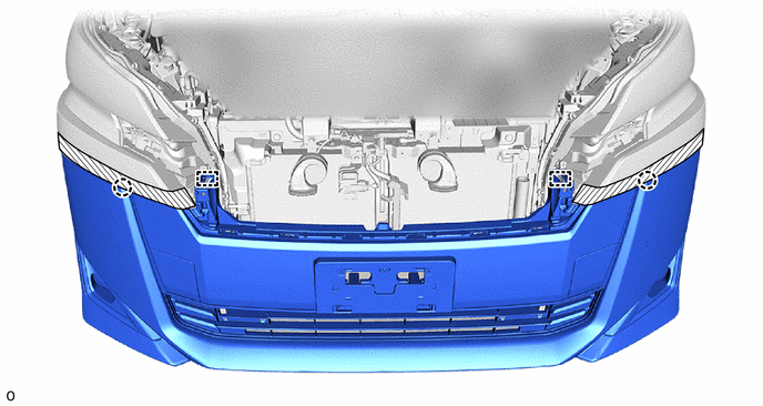
Remove the 4 clips and 2 screws.
-
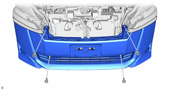
Put protective tape around the front bumper cover.

Protective Tape - - -
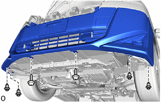
Remove the 3 clips and 2 bolts.
-
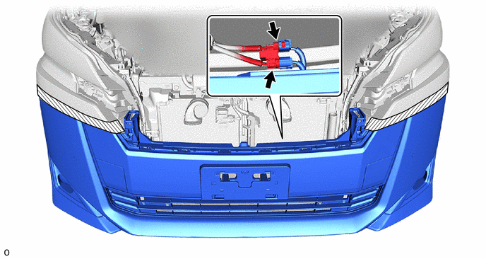
Disconnect the 2 connectors.
-
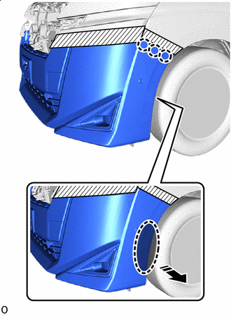

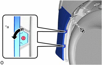
Place Hands Here Remove in this Direction Place your hand at the positions shown in the illustration and pull in the removal direction to detach the claw.
Tech Tips
Use the same procedure for the other side.
-
Detach the guide, claw and remove the front bumper cover.
-
-
REMOVE FRONT BUMPER ENERGY ABSORBER
-
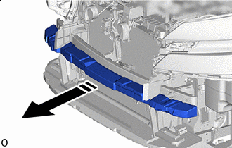
Remove in this Direction Remove the front bumper energy absorber as shown in the illustration.
-
-
REMOVE THERMISTOR ASSEMBLY
-
REMOVE HOOD LOCK SUPPORT BRACE SUB-ASSEMBLY
-
REMOVE FRONT BUMPER REINFORCEMENT SUB-ASSEMBLY
-
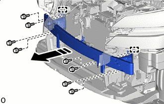
Remove in this Direction Remove the 8 bolts.
-
Detach the guide and remove the front bumper reinforcement sub-assembly as shown in the illustration.
-
-
REMOVE FRONT BUMPER SIDE SUPPORT LH
-
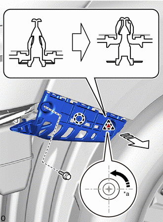
*a 90° Rotation Direction 
Remove in this Direction Remove the bolt.
-
Using a screwdriver, turn the clip 90° and remove the clip.
-
Detach the claw and remove front bumper side support LH as shown in the illustration.
-
-
REMOVE FRONT BUMPER SIDE SUPPORT RH
Tech Tips
Use the same procedure described for the LH side.
-
REMOVE FRONT WHEEL OPENING EXTENSION PAD LH
-
REMOVE FRONT WHEEL OPENING EXTENSION PAD RH