FRONT BUMPER(for ALPHARD) REMOVAL
CAUTION / NOTICE / HINT
The necessary procedures (adjustment, calibration, initialization or registration) that must be performed after parts are removed, installed or replaced during the front bumper cover installation/removal are shown below.
| Replacement Part or Procedure | Necessary Procedures | Effects/Inoperative Functions when not Performed | Link |
|---|---|---|---|
| Removal/installtaion of the front television camera assembly or the radiator grille | Television camera view adjustment | Panoramic view monitor system |
PROCEDURE
-
REMOVE RADIATOR COVER SUB-ASSEMBLY
-
REMOVE RADIATOR GRILLE
-
REMOVE FRONT BUMPER COVER
-
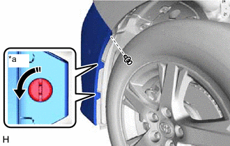
*a 90° 
Rotation Direction Using a screwdriver, turn the pin hold clip 90° and remove the 2 pin hold clips.
Tech Tips
Use the same procedure for the pin hold clips on the other side.
-
Remove the clip.
Tech Tips
Use the same procedure for the clip on the other side.
-
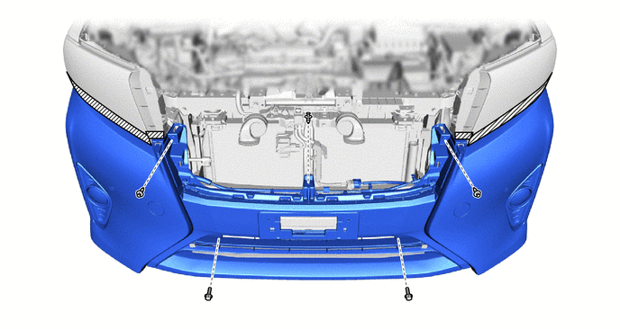
Remove the 4 clips and 2 screws.
-
Put protective tape around the front bumper cover.

Protective Tape - - -
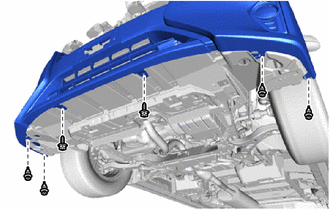
Remove the 3 clips and 2 bolts.
-
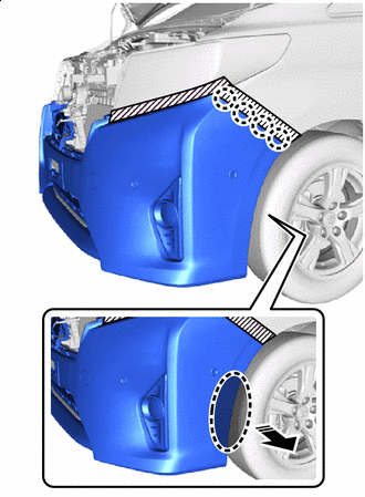

Place Hands Here Remove in this Direction Detach the claw as shown in the illustration.
-
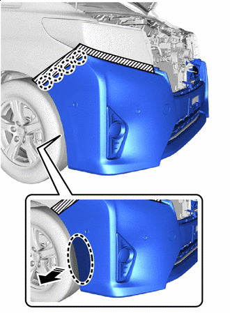
Place Hands Here Remove in this Direction Detach the claw as shown in the illustration.
-
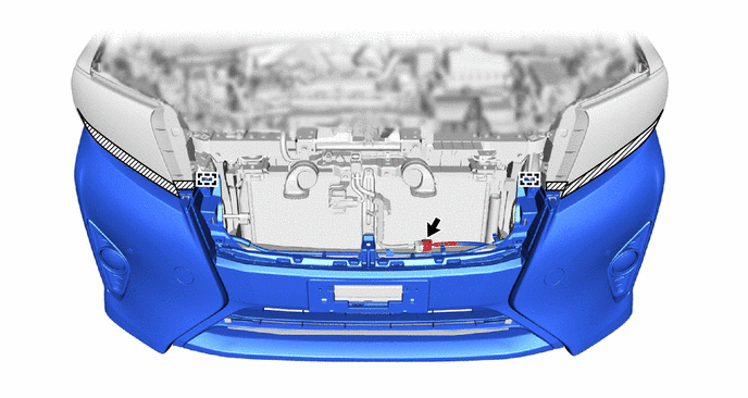
Disconnect the connector.
-
Detach the guide and remove the front bumper cover.
-
-
REMOVE FRONT BUMPER ENERGY ABSORBER
-
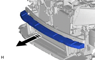
Remove in this Direction Remove the front bumper energy absorber as shown in the illustration.
-
-
REMOVE THERMISTOR ASSEMBLY
-
REMOVE HOOD LOCK SUPPORT BRACE SUB-ASSEMBLY
-
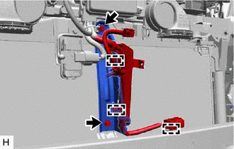
Detach the clamp.
-
Remove the 2 bolts and hood lock support brace sub-assembly.
-
-
REMOVE FRONT BUMPER REINFORCEMENT SUB-ASSEMBLY
-
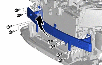
Remove in this Direction Remove the 8 bolts.
-
Remove the front bumper reinforcement sub-assembly as shown in the illustration.
-
-
REMOVE FRONT BUMPER SIDE SUPPORT LH
-
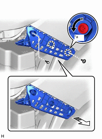
*a 90° Rotation Direction 
Remove in this Direction Remove the bolts.
-
Using a screwdriver, turn the clip 90° and remove the clip.
-
Detach the claw and remove the front bumper side support LH as shown in the illustration.
-
-
REMOVE FRONT BUMPER SIDE SUPPORT RH
Tech Tips
Use the same procedure described for the LH side.
-
REMOVE FRONT WHEEL OPENING EXTENSION PAD LH
-
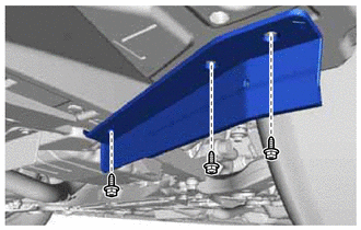
Remove the 3 screws and front wheel opening extension pad LH.
-
-
REMOVE FRONT WHEEL OPENING EXTENSION PAD RH
Tech Tips
Use the same procedure described for the LH side.