STOP LIGHT SWITCH INSTALLATION
CAUTION / NOTICE / HINT
Tech Tips
-
Use the same procedure for RHD and LHD vehicles.
-
The procedure listed below is for LHD vehicles.
PROCEDURE
-
INSTALL STOP LIGHT SWITCH MOUNTING ADJUSTER
-
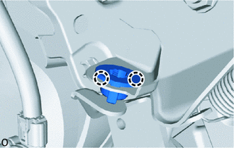
Attach the claw to install a new stop light switch mounting adjuster.
-
-
INSTALL STOP LIGHT SWITCH ASSEMBLY
-
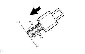
Insert the stop light switch assembly to the stop light switch mounting adjuster until the switch body slightly touches the brake pedal.
Note
Do not depress the brake pedal.
-
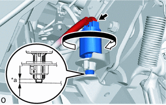
*a Protrusion Amount Measurement Area Rotate the stop light switch assembly clockwise by approximately one fourth of a rotation.
-
Check the protrusion amount of the shaft.
Standard 1.5 to 2.6 mm (0.0591 to 0.1024 in.) -
Connect the connector.
-
-
INSTALL NO. 1 INSTRUMENT PANEL UNDER COVER SUB-ASSEMBLY
for LHD:
for RHD:
-
INSTALL COWL SIDE TRIM BOARD LH (for LHD)
-
INSTALL COWL SIDE TRIM BOARD RH (for RHD)