HEADLIGHT ASSEMBLY(for VELLFIRE) DISASSEMBLY

CAUTION / NOTICE / HINT
The necessary procedures (adjustment, calibration, initialization or registration) that must be performed after parts are installed, removed or replaced during the headlight light control ECU sub-assembly LH removal/installation are shown below.
| Replacement Part or Procedure | Necessary Procedures | Effects/Inoperative Functions when not Performed | Link |
|---|---|---|---|
| Headlight light control ECU sub-assembly LH |
|
Automatic headlight beam level control system |
Note
Even if the headlight light control ECU sub-assembly RH is replaced with a new one, vehicle information registration and initialization are not necessary.
PROCEDURE
-
PRECAUTION
Note
-
Handle components indoors as much as possible to prevent foreign matter from entering and adhering to headlight assembly components.
-
Do not reuse parts which have reduced fastening ability due to thread damage.
-
Do not touch the inner surface of the lens and metallic surfaces as much as possible, or they may become dirty.
-
Do not allow metallic surfaces to become dirty, as such surfaces become damaged even if they are only lightly wiped with a soft cloth.
-
When installing components, make sure that the wire harness is not pinched or pulled.
-
Do not use solvent to clean components. Only clean them with a dry cloth.
Tech Tips
-
Use the same procedure for the RH and LH sides.
-
The procedure listed below is for the LH side.
-
-
REMOVE HEADLIGHT PROTECTOR LH
-
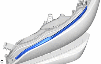
Remove the headlight protector LH.
Note
The headlight protector LH must not be reused.
-
-
REMOVE FRONT TURN SIGNAL LIGHT BULB
-
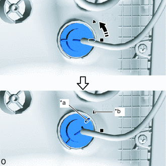
*a Matchmark *b Unlock Position Mark 
Counterclockwise Turn the bulb socket counterclockwise until the matchmark is aligned with the unlock position mark to disconnect the bulb socket.
-
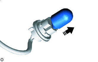
Remove in this Direction Remove the front turn signal light bulb from the bulb socket.
-
-
REMOVE HEADLIGHT COVER LH
-
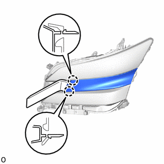
Using a moulding remover A, detach the claw.
-

Place Hands Here Place your hand in the open gap, detach the remaining claw, and then remove the headlight cover LH.
-
-
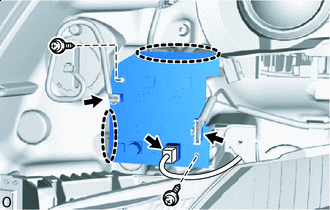
REMOVE HEADLIGHT LIGHT CONTROL ECU SUB-ASSEMBLY LH
-
REMOVE HEADLIGHT GASKET
-
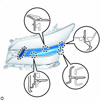
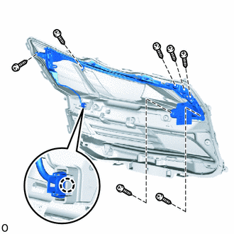
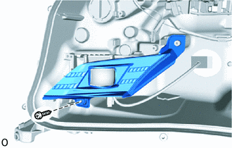
REMOVE HEADLIGHT LENS ASSEMBLY LH
-

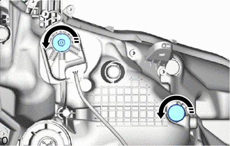
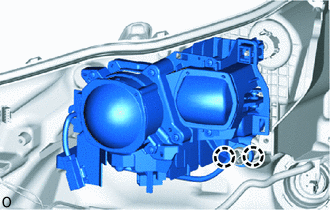
Remove the 8 screws.
-
Detach the claw.
Tech Tips
It is not necessary to detach the claw at the base point as the claw is detached in a later step.
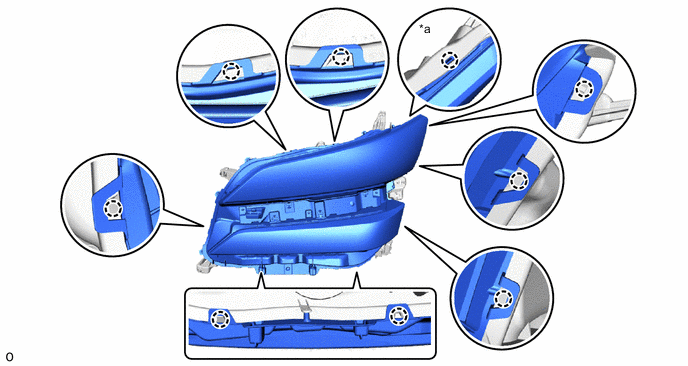
*a Base Point - - -
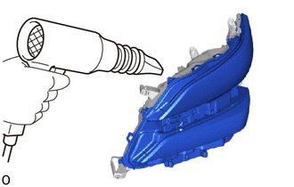
Using a dryer, heat the backside of the headlight assembly LH.
Note
If the headlight assembly LH is heated unevenly, it will deform or melt.
-
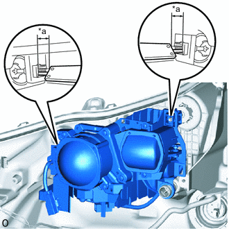
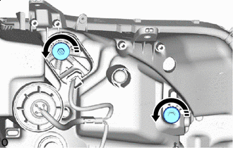
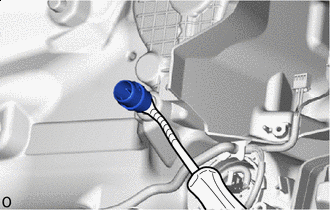
Turn the wire harness cap counterclockwise until the matchmark is stoped to disconnect the wire harness cap.
-
Using a T20H "TORX" driver, remove the "TORX" screw.
-
Turn the connector cap counterclockwise until the matchmark is stoped to remove the connector cap.
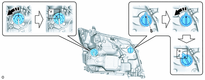
*a Matchmark - - Counterclockwise - - -
Disconnct the 2 connectors.
-
With the headlight lens assembly LH slightly lifted, cut the headlight lens gasket with scissors and disconnect the headlight lens assembly LH.
Tech Tips
-
If the headlight lens assembly LH cannot be removed even after heating, using a screwdriver, lift the headlight light lens assembly LH.
-
Tape the screwdriver tip before use.
-
-
Detach the claw at the base point to remove the headlight lens assembly LH.
Note
-
Do not touch the headlight lens assembly LH with bare hands.
-
If dirty, lightly wipe with a soft cloth.
-
-
-
REMOVE HEADLIGHT LENS GASKET
-
Remove the headlight lens gasket from the headlight lens assembly LH and headlight body.
-
-
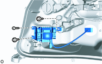
REMOVE CLEARANCE LIGHT LED UNIT ASSEMBLY LH
Note
-
Perform work using rubber gloves.
-
Do not touch the clearance light LED unit assembly LH and circuit sub-assembly with bare hands.
-
Do not allow metallic surfaces to become dirty, as such surfaces become damaged even if they are only lightly wiped with a soft cloth.
-
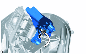
for Lens Side:
-
Detach the claw and disconnect the connector.
-
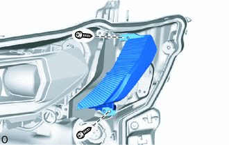
Remove the 7 screws and clearance light LED unit assembly LH.
-
-
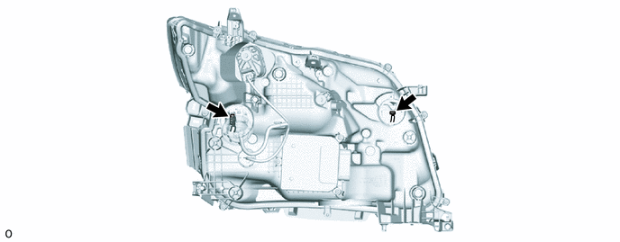
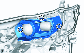
for Headlight Body Side:
-
Remove the 2 screws and clearance light LED unit assembly LH.
-
Disconnect the connector.
-
-
-
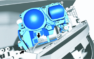
REMOVE NO. 2 CLEARANCE LIGHT UNIT ASSEMBLY LH
Note
-
Perform work using rubber gloves.
-
Do not touch the NO. 2 clearance light unit assembly LH and cornering light unit bezel and circuit sub-assembly with bare hands.
-
If dirty, lightly wipe with a soft cloth.
-
Place Hands Here Disconnect the 3 connectors.
-
Renove the 2 screws.
-
Place your hand at the location shown in the illustration, and remove the circuit sub-assembly.
-
Remove the 2 screws and No. 2 clearance light unit assembly LH.
-
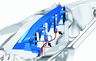
Disconnect the 2 connectors.
-
-
REMOVE CORNERING LIGHT UNIT ASSEMBLY LH
Note
-
Perform work using rubber gloves.
-
Do not touch the cornering light unit assembly LH, turn signal light reflector and cornering light unit bezel with bare hands.
-
Do not allow metallic surfaces to become dirty, as such surfaces become damaged even if they are only lightly wiped with a soft cloth.
-
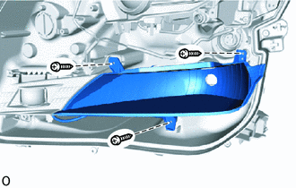
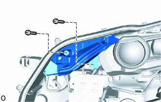
Remove the 3 screws and turn signal light reflector.
-
Remove the screw and cornering light unit bezel.
-
Remove the 3 screws and cornering light unit assembly LH.
-
-
REMOVE HEADLIGHT UNIT ASSEMBLY LH
Note
-
Perform work using rubber gloves.
-
Do not touch the headlight unit assembly LH and headlight unit bezel with bare hands.
-
Do not allow metallic surfaces to become dirty, as such surfaces become damaged even if they are only lightly wiped with a soft cloth.
-
Detach the claw and remove the headlight unit bezel.
-
Disconnect the 2 connectors.
-
*a Protrusion Amount Measurement Area Using a vernier caliper, measure and record the protrusion amount of the horizontal and vertical aiming screw.
-
Loosening in this Direction Loosen the horizontal and vertical aiming screw 5 rotations.
-
Detach the claw and disconnect the headlight unit assembly LH from the pivot collar.
-
Loosening in this Direction While holding the headlight unit assembly LH with one hand so that it does not fall over, loosen the horizontal and vertical aiming screw until the headlight unit assembly LH is disconnected.
-

Protective Tape Using a clip remover, remove the pivot collar and attach the claw to install it to the headlight unit assembly LH.
Tech Tips
Tape the clip remover tip before use.
-