LIGHTING SYSTEM High Beam Headlight Circuit
DESCRIPTION
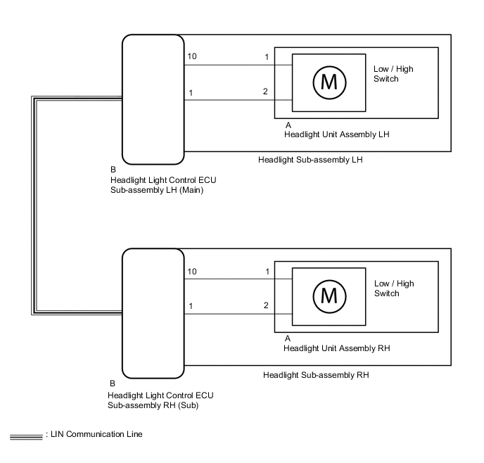
The illumination of the high beam headlights is controlled by the headlight light control ECU sub-assembly.
WIRING DIAGRAM
CAUTION / NOTICE / HINT
Note
-
Inspect the bulbs for circuits related to this system before performing the following inspection procedure.
-
After the headlight light control ECU sub-assembly LH (main) is replaced, vehicle information registration and initialization are necessary.
-
The light system (exterior) uses the CAN communication system and multiplex communication system (LIN). First perform the communication function checks in "How to Proceed with Troubleshooting" to confirm that there are no communication malfunctions before proceeding with troubleshooting.
PROCEDURE
-
PERFORM ACTIVE TEST USING GTS (HEAD LIGHT HI)
-
Using the GTS, perform the Active Test.
Body Electrical > Main Body > Active TestTester Display Measurement Item Control Range Diagnostic Note Head Light Hi Illuminates the high beam headlights ON or OFF -
Body Electrical > Main Body > Active TestTester Display Head Light Hi Result Result Proceed to The Active Test is performed normally A The Active Test is not performed normally for the right side light only B The Active Test is not performed normally for the left side light only C
A 
PROCEED TO NEXT SUSPECTED AREA SHOWN IN PROBLEM SYMPTOMS TABLE Click here
C 
INSPECT HEADLIGHT HOUSING SUB-ASSEMBLY LH (WIRE HARNESS ASSEMBLY) Click here
B 
-
-
INSPECT HEADLIGHT HOUSING SUB-ASSEMBLY RH (WIRE HARNESS ASSEMBLY)
-
Remove the headlight sub-assembly RH.
for ALPHARD:
for VELLFIRE:
-
Remove the headlight unit assembly RH from the headlight sub-assembly RH.
for ALPHARD:
for VELLFIRE:
-
Measure the resistance according to the value(s) in the table below.
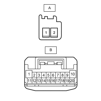
Standard Resistance Tester Connection Condition Specified Condition B-10 - A-1 Always Below 1 Ω B-1 - A-2 Always Below 1 Ω Result Proceed to OK NG
NG
REPLACE HEADLIGHT HOUSING SUB-ASSEMBLY RH (WIRE HARNESS ASSEMBLY) for ALPHARD: REPLACE HEADLIGHT HOUSING SUB-ASSEMBLY RH (WIRE HARNESS ASSEMBLY) Click here
REPLACE HEADLIGHT HOUSING SUB-ASSEMBLY RH (WIRE HARNESS ASSEMBLY) for VELLFIRE: REPLACE HEADLIGHT HOUSING SUB-ASSEMBLY RH (WIRE HARNESS ASSEMBLY) Click hereOK
-
-
REPLACE HEADLIGHT UNIT ASSEMBLY RH
-
Temporarily replace the headlight unit assembly RH with a new or normally functioning one.
for ALPHARD:
for VELLFIRE:
-
Check that the operation of the lighting system returns to normal.
Result Proceed to OK NG
OK
END (HEADLIGHT UNIT ASSEMBLY RH WAS DEFECTIVE)
NG
REPLACE HEADLIGHT LIGHT CONTROL ECU SUB-ASSEMBLY RH (SUB) Click here
-
-
INSPECT HEADLIGHT HOUSING SUB-ASSEMBLY LH (WIRE HARNESS ASSEMBLY)
-
Remove the headlight sub-assembly LH.
for ALPHARD:
for VELLFIRE:
-
Remove the headlight unit assembly LH from the headlight sub-assembly LH.
for ALPHARD:
for VELLFIRE:
-
Measure the resistance according to the value(s) in the table below.
Standard Resistance Tester Connection Condition Specified Condition B-10 - A-1 Always Below 1 Ω B-1 - A-2 Always Below 1 Ω Result Proceed to OK NG
NG
REPLACE HEADLIGHT HOUSING SUB-ASSEMBLY LH (WIRE HARNESS ASSEMBLY) for ALPHARD: REPLACE HEADLIGHT HOUSING SUB-ASSEMBLY LH (WIRE HARNESS ASSEMBLY) Click here
REPLACE HEADLIGHT HOUSING SUB-ASSEMBLY LH (WIRE HARNESS ASSEMBLY) for VELLFIRE: REPLACE HEADLIGHT HOUSING SUB-ASSEMBLY LH (WIRE HARNESS ASSEMBLY) Click hereOK
-
-
REPLACE HEADLIGHT UNIT ASSEMBLY LH
-
Temporarily replace the headlight unit assembly LH with a new or normally functioning one.
for ALPHARD:
for VELLFIRE:
-
Check that the operation of the lighting system returns to normal.
Result Proceed to OK NG
OK
END (HEADLIGHT UNIT ASSEMBLY LH WAS DEFECTIVE)
NG
REPLACE HEADLIGHT LIGHT CONTROL ECU SUB-ASSEMBLY LH (MAIN) Click here
-