AUTOMATIC HIGH BEAM SYSTEM TERMINALS OF ECU
-
CHECK MAIN BODY ECU (MULTIPLEX NETWORK BODY ECU) AND JUNCTION BLOCK ASSEMBLY LH
-
Remove the main body ECU (multiplex network body ECU) from the junction block assembly LH.
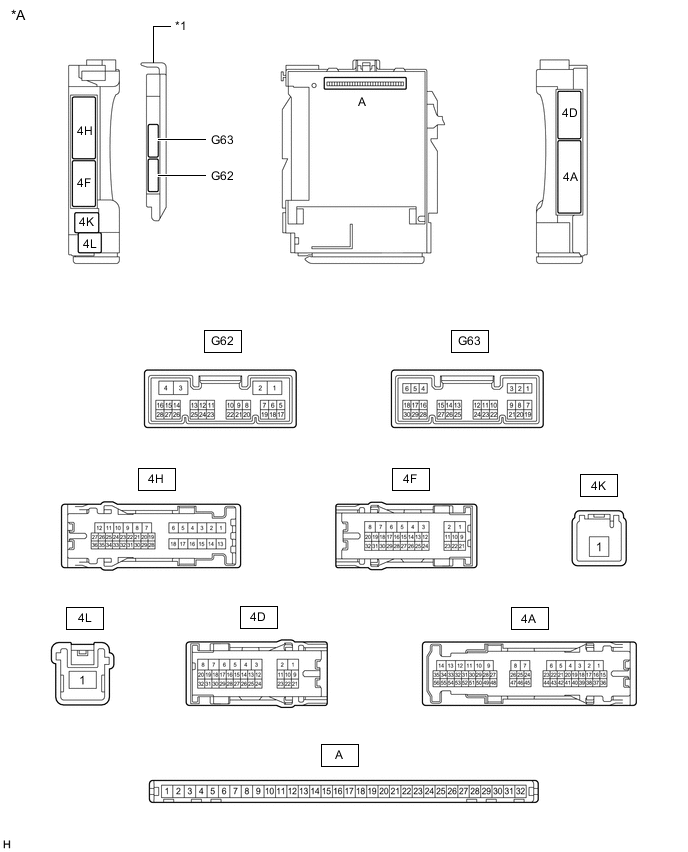
*A Main Body ECU (Multiplex Network BodyECU) with 2 connectors - - *1 Main Body ECU (Multiplex Network Body ECU) - - 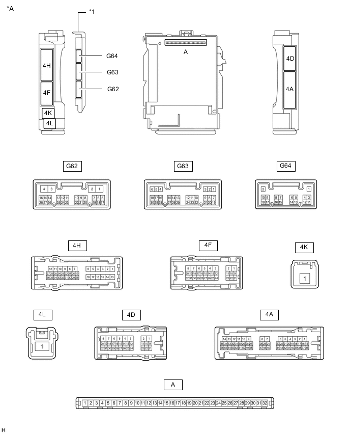
*A Main Body ECU (Multiplex Network Body ECU) with 3 connectors - - *1 Main Body ECU (Multiplex Network Body ECU) - - -
Connect the junction block assembly LH connectors.
-
Measure the voltage and resistance according to the value(s) in the table below.
Terminal No. (Symbol) Wiring Color Terminal Description Condition Specified Condition A-32 (IG) - Body ground - Ignition power supply Engine switch off Below 1 V Engine switch on (IG) 11 to 14 V A-31 (BECU) - Body ground - Battery power supply Always 11 to 14 V A-30 (ACC) - Body ground - ACC power supply Engine switch off Below 1 V Engine switch on (ACC) 11 to 14 V A-11 (GND1) - Body ground - Ground Always Below 1 Ω -
Install the main body ECU (multiplex network body ECU).
-
Measure the voltage and check the waveform between each connector terminal using an oscilloscope according to the value(s) in the table below.
Terminal No. (Symbol) Wiring Color Terminal Description Condition Specified Condition G63-20 (CLTS) - Body ground R - Body ground Automatic light control sensor signal input Engine switch off Below 1 V Engine switch on (IG), headlight dimmer switch in AUTO position, material which blocks light used to cover and then uncover top of automatic light control sensor Pulse generation generation
(See waveform 1)
G63-24 (HU) - Body ground Y - Body ground Headlight dimmer switch high signal input
-
Headlight dimmer switch in low position (When vehicle has the dimmer switch off position)
-
Low beams illuminated with headlight dimmer switch in AUTO position (When vehicle does not have the dimmer switch off position)*
11 to 14 V Headlight dimmer switch in high position Below 1 V G63-13 (CANL) - Body ground W - Body ground CAN communication line Engine switch on (IG) Pulse generation G63-14 (CANH) - Body ground R - Body ground CAN communication line Engine switch on (IG) Pulse generation G62-23 (AHBI) - Body ground LG - Body ground Auto high beam switch signal input Automatic high beam switch on Below 1 V Automatic high beam switch off 11 to 14 V *: Low beams do not illuminate in daytime mode. It is necessary to cover the top of the automatic light control sensor with a material which blocks light to activate nighttime mode.
-
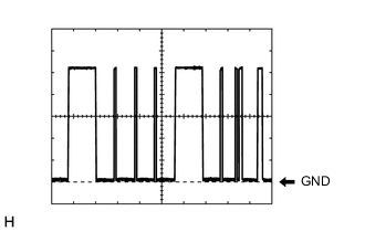
Waveform 1
Item Content Terminal No. (Symbol) G63-20 (CLTS) - Body ground Tool Setting 2 V/DIV., 10 ms./DIV. Condition Engine switch on (IG), headlight dimmer switch in AUTO position, material which blocks light used to cover and then uncover top of automatic light control sensor Tech Tips
The communication waveform changes according to the surrounding brightness.
-
-
-
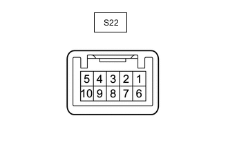
CHECK INNER REAR VIEW MIRROR ASSEMBLY
-
Measure the voltage, resistance and check the waveform between each connector terminal using an oscilloscope according to the value(s) in the table below.
Terminal No. (Symbol) Wiring Color Terminal Description Condition Specified Condition S22-2 (E) - Body ground W-B - Body ground Ground Always Below 1 Ω S22-1 (IG) - Body ground R - Body ground Ignition power supply Engine switch off Below 1 V Engine switch on (IG) 11 to 14 V S22-9 (CANH) - Body ground R - Body ground CAN communication line Engine switch on (IG) Pulse generation S22-10 (CANL) - Body ground W - Body ground CAN communication line Engine switch on (IG) Pulse generation
-