LIGHTING SYSTEM Clearance Light/Daytime Running Light Circuit
DESCRIPTION
-
Clearance light function
-
The clearance light function illuminates the clearance light/daytime running light* LEDs when the main body ECU (multiplex network body ECU) inputs the light control switch position signals to the headlight light control ECU assembly.
*: w/ Cornering Light
-
Daytime running light function (w/ Cornering Light)
-
The daytime running light function (w/ Cornering Light) illuminates the clearance light/daytime running light LEDs in the clearance light assembly at the daytime running light brightness level (brighter than the clearance light level) when the main body ECU (multiplex network body ECU) inputs the light control switch position signals, engine speed signals and surrounding brightness signals to the headlight light control ECU assembly, and the operation conditions of the daytime running light function are met.
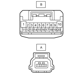
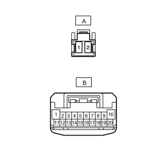
WIRING DIAGRAM
-
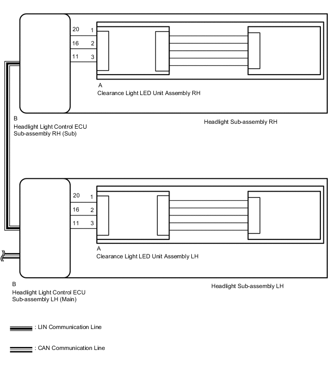
for ALPHARD (w/ Cornering Light)
-
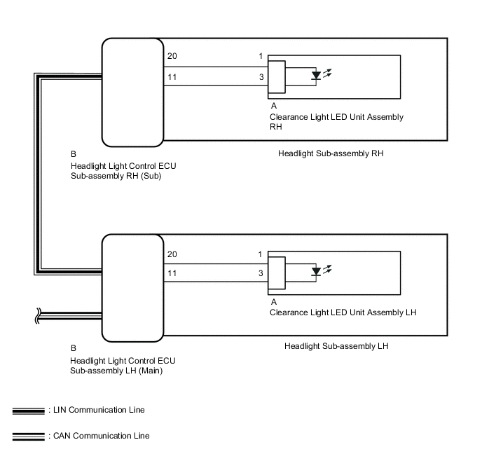
for ALPHARD (w/o Cornering Light)
-
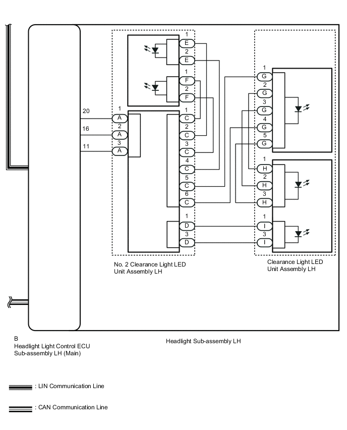
for VELLFIRE (w/ Cornering Light)
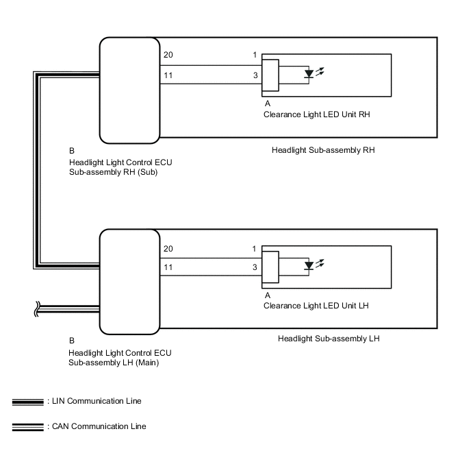
Figure 1. for RH Side
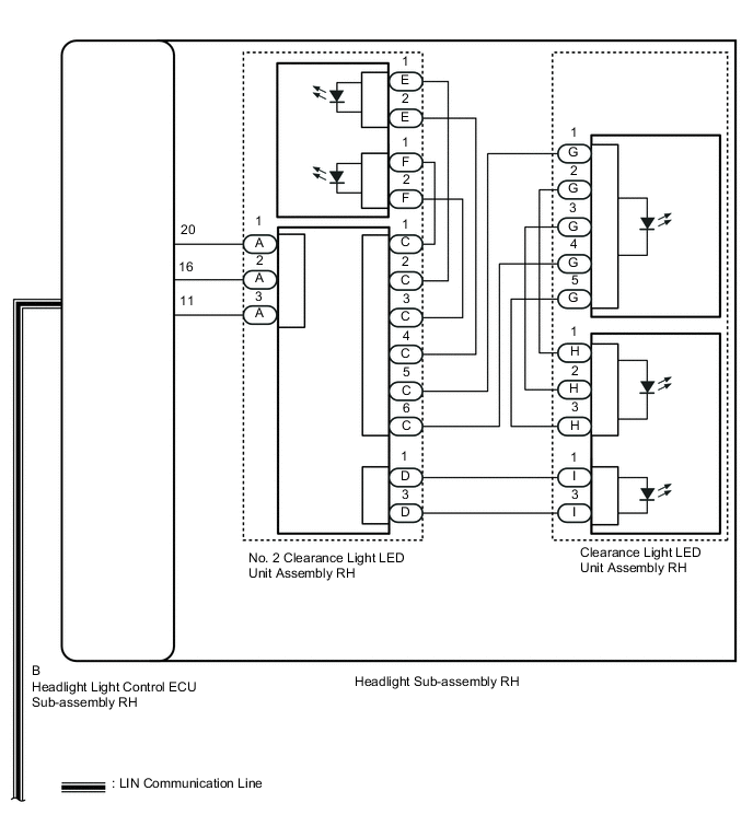
Figure 2. for LH Side
-
for VELLFIRE (w/o Cornering Light)
CAUTION / NOTICE / HINT
Note
Inspect the fuses for circuits related to this system before performing the following inspection procedure.
PROCEDURE
-
CHECK VEHICLE TYPE
-
Check vehicle type.
Result Proceed to w/ Cornering Light w/o Cornering Light
w/o Cornering Light 
PERFORM ACTIVE TEST USING GTS (CLEARANCE LIGHT) Click here
w/ Cornering Light 
-
-
PERFORM ACTIVE TEST USING GTS (DAYTIME RUNNING LIGHT)
-
Using the GTS, perform the Active Test.
Body Electrical > HL AutoLeveling > Active TestTester Display Measurement Item Control Range Diagnostic Note Clearance Light Illuminates cornering lights ON or OFF - Daytime Running Light Illuminates daytime running lights ON or OFF -
Body Electrical > HL AutoLeveling > Active TestTester Display Clearance Light
Body Electrical > HL AutoLeveling > Active TestTester Display Daytime Running Light Result Result Proceed to The Active Test is performed normally A The Active Test is not performed normally for the right side light only B The Active Test is not performed normally for the left side light only C
A 
PROCEED TO NEXT SUSPECTED AREA SHOWN IN PROBLEM SYMPTOMS TABLE Click here
C
CHECK CLEARANCE/DAYTIME RUNNING LIGHT Click here
B
-
-
CHECK CLEARANCE/DAYTIME RUNNING LIGHT
-
Remove the headlight sub-assembly RH.
for ALPHARD:
for VELLFIRE:
-
Remove the headlight light control ECU sub-assembly RH (sub) from the headlight sub-assembly RH.
-
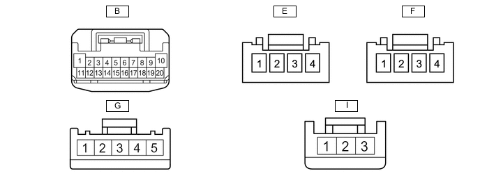
Check the light illumination condition when the battery voltage is applied to each connector terminal.
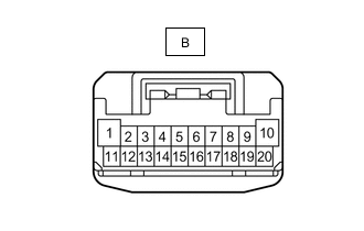
Standard Battery Connection Specified Condition Battery positive (+) terminal - B-20
Battery negative (-) terminal - B-16
Battery negative (-) terminal - B-11
LED illuminates* Note
-
Do not apply battery voltage to the connector terminals for 30 seconds or more. Otherwise, the internal circuit may become damaged.
-
When checking more than once, wait 1 minute or more between each check
Tech Tips
*: Brighter than normal clearance light or daytime running light illumination
Result Proceed to All LEDs Illuminate All LEDs do not Illuminate Some LEDs do not Illuminate (for ALPHARD) Some LEDs do not Illuminate (for VELLFIRE) -
All LEDs Illuminate
REPLACE HEADLIGHT LIGHT CONTROL ECU SUB-ASSEMBLY RH (SUB) Click here
Some LEDs do not Illuminate (for ALPHARD)
REPLACE CLEARANCE LIGHT LED UNIT ASSEMBLY RH Click here
Some LEDs do not Illuminate (for VELLFIRE)
CHECK HEADLIGHT SUB-ASSEMBLY RH Click here
All LEDs do not Illuminate
-
-
CHECK HEADLIGHT HOUSING SUB-ASSEMBLY RH (WIRE HARNESS ASSEMBLY)
-
Remove the headlight sub-assembly RH.
for ALPHARD:
for VELLFIRE:
-
Remove the headlight light control ECU sub-assembly RH (sub) from the headlight sub-assembly RH.
-
Remove the clearance light LED unit from the headlight sub-assembly RH.
for ALPHARD:
for VELLFIRE:
-
Measure the resistance according to the value(s) in the table below.
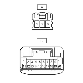
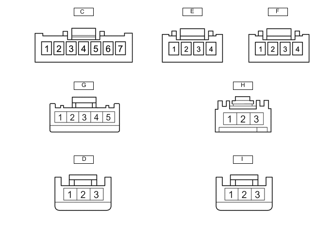
Standard Resistance Tester Connection Condition Specified Condition B-20 - A-1 Always Below 1 Ω B-16 - A-2 Always Below 1 Ω B-11 - A-3 Always Below 1 Ω Result Proceed to OK (for ALPHARD) OK (for VELLFIRE) NG
OK (for ALPHARD)
REPLACE CLEARANCE LIGHT LED UNIT ASSEMBLY RH Click here
OK (for VELLFIRE)
REPLACE NO. 2 CLEARANCE LIGHT LED UNIT ASSEMBLY RH Click here
NG
REPLACE HEADLIGHT HOUSING SUB-ASSEMBLY RH (WIRE HARNESS ASSEMBLY) for ALPHARD: REPLACE HEADLIGHT HOUSING SUB-ASSEMBLY RH (WIRE HARNESS ASSEMBLY) Click here
REPLACE HEADLIGHT HOUSING SUB-ASSEMBLY RH (WIRE HARNESS ASSEMBLY) for VELLFIRE: REPLACE HEADLIGHT HOUSING SUB-ASSEMBLY RH (WIRE HARNESS ASSEMBLY) Click here -
-
CHECK HEADLIGHT SUB-ASSEMBLY RH
-
Remove the headlight sub-assembly RH.
-
Remove the No. 2 clearance light LED unit assembly RH from the headlight sub-assembly RH.
-
Remove the clearance light LED unit assembly from the headlight sub-assembly RH.
-
Measure the resistance according to the value(s) in the table below.
Standard Resistance Tester Connection Condition Specified Condition C-1 - F-1 Always Below 1 Ω C-2 - E-1 Always Below 1 Ω C-3 - F-2 Always Below 1 Ω C-4 - E-2 Always Below 1 Ω C-5 - G-1 Always Below 1 Ω C-6 - G-4 Always Below 1 Ω D-1 - I-1 Always Below 1 Ω D-3 - I-3 Always Below 1 Ω G-2 - H-1 Always Below 1 Ω G-3 - H-2 Always Below 1 Ω G-5 - H-3 Always Below 1 Ω Result Proceed to OK NG
NG
REPLACE HEADLIGHT SUB-ASSEMBLY RH Click here
OK
-
-
CHECK NO. 2 CLEARANCE LIGHT LED UNIT ASSEMBLY RH
-
Remove the headlight sub-assembly RH.
-
Remove the headlight light control ECU sub-assembly RH (sub) from the headlight sub-assembly RH.
-
Remove the No. 2 clearance light LED unit assembly RH from the headlight sub-assembly RH.
-
Remove the clearance light LED unit assembly RH from the headlight sub-assembly RH.
-
Connect connectors A, C, D, E and F to the No. 2 clearance light LED unit assembly RH.
-
Measure the voltage according to the value(s) in the table below.
Standard Voltage Tester Connection Condition Specified Condition I-1 - I-3 Battery voltage applied between B-20 (battery positive [+]) and B-11 and B-16 (battery negative [-]) terminals 11 to 14 V G-1 - G-4 11 to 14 V Result Proceed to OK NG
OK
REPLACE CLEARANCE LIGHT LED UNIT ASSEMBLY Click here
NG
REPLACE NO. 2 CLEARANCE LIGHT LED UNIT ASSEMBLY RH Click here
-
-
CHECK CLEARANCE/DAYTIME RUNNING LIGHT
-
Remove the headlight sub-assembly LH.
for ALPHARD:
for VELLFIRE:
-
Remove the headlight light control ECU sub-assembly LH (main) from the headlight sub-assembly LH.
-
Check the light illumination condition when the battery voltage is applied to each connector terminal.
Standard Battery Connection Specified Condition Battery positive (+) terminal - B-20
Battery negative (-) terminal - B-16
Battery negative (-) terminal - B-11
LED illuminates* Note
-
Do not apply battery voltage to the connector terminals for 30 seconds or more. Otherwise, the internal circuit may become damaged.
-
When checking more than once, wait 1 minute or more between each check.
Tech Tips
*: Brighter than normal clearance light or daytime running light illumination.
Result Proceed to All LEDs Illuminate All LEDs do not Illuminate Some LEDs do not Illuminate (for ALPHARD) Some LEDs do not Illuminate (for VELLFIRE) -
All LEDs Illuminate
REPLACE HEADLIGHT LIGHT CONTROL ECU SUB-ASSEMBLY LH (MAIN) Click here
Some LEDs do not Illuminate (for ALPHARD)
REPLACE CLEARANCE LIGHT LED UNIT ASSEMBLY LH Click here
Some LEDs do not Illuminate (for VELLFIRE)
CHECK HEADLIGHT SUB-ASSEMBLY LH Click here
All LEDs do not Illuminate
-
-
CHECK HEADLIGHT HOUSING SUB-ASSEMBLY LH (WIRE HARNESS ASSEMBLY)
-
Remove the headlight sub-assembly LH.
for ALPHARD:
for VELLFIRE:
-
Remove the headlight light control ECU sub-assembly LH (main) from the headlight sub-assembly LH.
-
Remove the clearance light LED unit from the headlight sub-assembly LH.
for ALPHARD:
for VELLFIRE:
-
Measure the resistance according to the value(s) in the table below.
Standard Resistance Tester Connection Condition Specified Condition B-20 - A-1 Always Below 1 Ω B-16 - A-2 Always Below 1 Ω B-11 - A-3 Always Below 1 Ω Result Proceed to OK (for ALPHARD) OK (for VELLFIRE) NG
OK (for ALPHARD)
REPLACE CLEARANCE LIGHT LED UNIT ASSEMBLY LH Click here
OK (for VELLFIRE)
REPLACE NO. 2 CLEARANCE LIGHT LED UNIT ASSEMBLY LH Click here
NG
REPLACE HEADLIGHT HOUSING SUB-ASSEMBLY LH (WIRE HARNESS ASSEMBLY) for ALPHARD: REPLACE HEADLIGHT HOUSING SUB-ASSEMBLY LH (WIRE HARNESS ASSEMBLY) Click here
REPLACE HEADLIGHT HOUSING SUB-ASSEMBLY LH (WIRE HARNESS ASSEMBLY) for VELLFIRE: REPLACE HEADLIGHT HOUSING SUB-ASSEMBLY LH (WIRE HARNESS ASSEMBLY) Click here -
-
CHECK HEADLIGHT SUB-ASSEMBLY LH
-
Remove the headlight sub-assembly LH.
-
Remove the No. 2 clearance light LED unit assembly LH from the headlight sub-assembly LH.
-
Remove the clearance light LED unit assembly LH from the headlight sub-assembly LH.
-
Measure the resistance according to the value(s) in the table below.
Standard Resistance Tester Connection Condition Specified Condition C-1 - F-1 Always Below 1 Ω C-2 - E-1 Always Below 1 Ω C-3 - F-2 Always Below 1 Ω C-4 - E-2 Always Below 1 Ω C-5 - G-1 Always Below 1 Ω C-6 - G-4 Always Below 1 Ω D-1 - I-1 Always Below 1 Ω D-3 - I-3 Always Below 1 Ω G-2 - H-1 Always Below 1 Ω G-3 - H-2 Always Below 1 Ω G-5 - H-3 Always Below 1 Ω Result Proceed to OK NG
NG
REPLACE HEADLIGHT SUB-ASSEMBLY LH Click here
OK
-
-
CHECK NO. 2 CLEARANCE LIGHT LED UNIT ASSEMBLY LH
-
Remove the headlight sub-assembly LH.
-
Remove the headlight light control ECU sub-assembly LH (main) from the headlight sub-assembly LH.
-
Remove the No. 2 clearance light LED unit assembly LH from the headlight sub-assembly LH.
-
Remove the clearance light LED unit assembly LH from the headlight sub-assembly LH.
-
Connect connectors A, C, D, E and F to the No. 2 clearance light LED unit assembly LH.
-
Measure the voltage according to the value(s) in the table below.
Standard Voltage Tester Connection Condition Specified Condition I-1 - I-3 Battery voltage applied between B-20 (battery positive [+]) and B-11 and B-16 (battery negative [-]) terminals 11 to 14 V G-1 - G-4 11 to 14 V Result Proceed to OK NG
OK
REPLACE CLEARANCE LIGHT LED UNIT ASSEMBLY Click here
NG
REPLACE NO. 2 CLEARANCE LIGHT LED UNIT ASSEMBLY LH Click here
-
-
PERFORM ACTIVE TEST USING GTS (CLEARANCE LIGHT)
-
Using the GTS, perform the Active Test.
Body Electrical > HL AutoLeveling > Active TestTester Display Measurement Item Control Range Diagnostic Note Clearance Light Illuminates cornering lights ON or OFF -
Body Electrical > HL AutoLeveling > Active TestTester Display Clearance Light Result Result Proceed to The Active Test is performed normally A The Active Test is not performed normally for the right side light only B The Active Test is not performed normally for the left side light only C
A
PROCEED TO NEXT SUSPECTED AREA SHOWN IN PROBLEM SYMPTOMS TABLE Click here
C
CHECK CLEARANCE LIGHT Click here
B
-
-
CHECK CLEARANCE LIGHT
-
Remove the headlight sub-assembly RH.
for ALPHARD:
for VELLFIRE:
-
Remove the headlight light control ECU sub-assembly RH (sub) from the headlight sub-assembly RH.
-
Check the light illumination condition when the battery voltage is applied to each connector terminal.
Standard Battery Connection Specified Condition Battery positive (+) terminal - B-20
Battery negative (-) terminal - B-11
LED illuminates Note
-
Do not apply battery voltage to the connector terminals for 30 seconds or more. Otherwise, the internal circuit may become damaged.
-
When checking more than once, wait 1 minute or more between each check.
Result Proceed to OK NG (for ALPHARD) NG (for VELLFIRE) -
OK
REPLACE HEADLIGHT LIGHT CONTROL ECU SUB-ASSEMBLY RH (SUB) Click here
NG (for VELLFIRE)
CHECK HEADLIGHT HOUSING SUB-ASSEMBLY RH (WIRE HARNESS ASSEMBLY) Click here
NG (for ALPHARD)
-
-
CHECK HEADLIGHT HOUSING SUB-ASSEMBLY RH (WIRE HARNESS ASSEMBLY)
-
Remove the headlight sub-assembly RH.
-
Remove the headlight light control ECU sub-assembly RH (sub) from the headlight sub-assembly RH.
-
Disconnect the clearance light LED unit RH connector.
-
Measure the resistance according to the value(s) in the table below.
Standard Resistance Tester Connection Condition Specified Condition B-20 - A-1 Always Below 1 Ω B-11 - A-3 Always Below 1 Ω Result Proceed to OK NG
OK
REPLACE CLEARANCE LIGHT LED UNIT ASSEMBLY RH Click here
NG
REPLACE HEADLIGHT HOUSING SUB-ASSEMBLY RH (WIRE HARNESS ASSEMBLY) Click here
-
-
CHECK HEADLIGHT HOUSING SUB-ASSEMBLY RH (WIRE HARNESS ASSEMBLY)
-
Remove the headlight sub-assembly RH.
-
Remove the headlight light control ECU sub-assembly RH (sub) from the headlight sub-assembly RH.
-
Remove the clearance light LED unit assembly RH from the headlight sub-assembly RH.
-
Measure the resistance according to the value(s) in the table below.
Standard Resistance Tester Connection Condition Specified Condition B-20 - A-1 Always Below 1 Ω B-11 - A-2 Always Below 1 Ω Result Proceed to OK NG
OK
REPLACE CLEARANCE LIGHT LED UNIT ASSEMBLY RH Click here
NG
REPLACE HEADLIGHT HOUSING SUB-ASSEMBLY RH (WIRE HARNESS ASSEMBLY) Click here
-
-
CHECK CLEARANCE LIGHT
-
Remove the headlight sub-assembly LH.
for ALPHARD:
for VELLFIRE:
-
Remove the headlight light control ECU sub-assembly LH (main) from the headlight sub-assembly LH.
-
Check the light illumination condition when the battery voltage is applied to each connector terminal.
Standard Battery Connection Specified Condition Battery positive (+) terminal - B-20
Battery negative (-) terminal - B-11
LED illuminates Note
-
Do not apply battery voltage to the connector terminals for 30 seconds or more. Otherwise, the internal circuit may become damaged.
-
When checking more than once, wait 1 minute or more between each check.
Result Proceed to OK NG (for ALPHARD) NG (for VELLFIRE) -
OK
REPLACE HEADLIGHT LIGHT CONTROL ECU SUB-ASSEMBLY LH (MAIN) Click here
NG (for VELLFIRE)
CHECK HEADLIGHT HOUSING SUB-ASSEMBLY LH (WIRE HARNESS ASSEMBLY) Click here
NG (for ALPHARD)
-
-
CHECK HEADLIGHT HOUSING SUB-ASSEMBLY LH (WIRE HARNESS ASSEMBLY)
-
Remove the headlight sub-assembly LH.
-
Remove the headlight light control ECU sub-assembly LH (main) from the headlight sub-assembly LH.
-
Disconnect the clearance light LED unit LH connector.
-
Measure the resistance according to the value(s) in the table below.
Standard Resistance Tester Connection Condition Specified Condition B-20 - A-1 Always Below 1 Ω B-11 - A-3 Always Below 1 Ω Result Proceed to OK NG
OK
REPLACE CLEARANCE LIGHT LED UNIT ASSEMBLY LH Click here
NG
REPLACE HEADLIGHT HOUSING SUB-ASSEMBLY LH (WIRE HARNESS ASSEMBLY) Click here
-
-
CHECK HEADLIGHT HOUSING SUB-ASSEMBLY LH (WIRE HARNESS ASSEMBLY)
-
Remove the headlight sub-assembly RH.
-
Remove the headlight light control ECU sub-assembly LH (main) from the headlight sub-assembly RH.
-
Remove the clearance light LED unit assembly RH from the headlight sub-assembly RH.
-
Measure the resistance according to the value(s) in the table below.
Standard Resistance Tester Connection Condition Specified Condition B-20 - A-1 Always Below 1 Ω B-11 - A-2 Always Below 1 Ω Result Proceed to OK NG
OK
REPLACE CLEARANCE LIGHT LED UNIT ASSEMBLY LH Click here
NG
REPLACE HEADLIGHT HOUSING SUB-ASSEMBLY LH (WIRE HARNESS ASSEMBLY) Click here
-