LIGHTING SYSTEM Headlight Dimmer Switch Circuit
DESCRIPTION
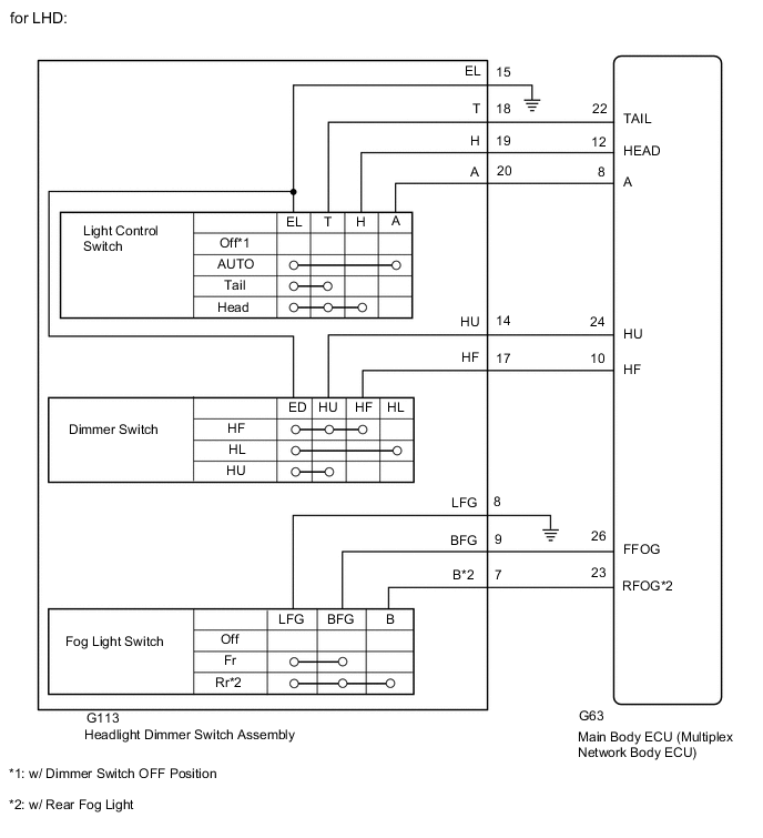
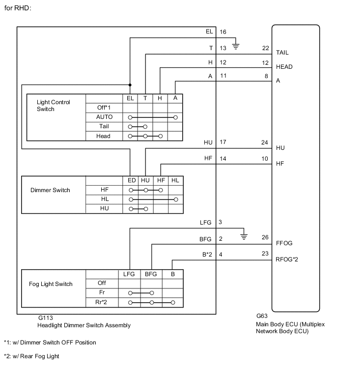
The main body ECU (multiplex network body ECU) receives light control switch signals, dimmer switch signals, fog light switch (front/rear*) signals from the headlight dimmer switch.
-
*: w/ Rear Fog Light
WIRING DIAGRAM
CAUTION / NOTICE / HINT
Note
-
If the main body ECU (multiplex network body ECU) is replaced, refer to the Service Bulletin.
-
As the door control battery is installed between the vehicle battery and main body ECU (multiplex network body ECU), first perform the inspections in On-Vehicle Inspection to confirm that there are no malfunctions in the power source circuit for the main body ECU (multiplex network body ECU) before performing this troubleshooting procedure.
PROCEDURE
-
READ VALUE USING GTS (HEADLIGHT DIMMER SWITCH)
-
Using the GTS, read the Data List.
Body Electrical > Main Body > Data ListTester Display Measurement Item Range Normal Condition Diagnostic Note Dimmer SW Headlight dimmer switch high position signal ON or OFF ON: Headlight dimmer switch in high or high flash position
OFF: Headlight dimmer switch in low position
- Passing Light SW Headlight dimmer switch high flash position (pass) signal ON or OFF ON: Headlight dimmer switch in high flash position
OFF: Headlight dimmer switch not in high flash position
- Rear Fog Light SW Rear fog light switch signal ON or OFF ON: Rear fog light switch on
OFF: Rear fog light switch off
w/ Rear Fog Light Front Fog Light SW Front fog light switch signal ON or OFF ON: Front fog light switch on
OFF: Front fog light switch off
- Auto Light SW Headlight dimmer switch (light control switch) AUTO position signal ON or OFF ON: Headlight dimmer switch (light control switch) in AUTO position
OFF: Headlight dimmer switch (light control switch) not in AUTO position
- Head Light SW (Head) Headlight dimmer switch (light control switch) head position signal ON or OFF ON: Headlight dimmer switch (light control switch) in head position
OFF: Headlight dimmer switch (light control switch) not in head position
- Head Light SW (Tail) Headlight dimmer switch (light control switch) tail position signal ON or OFF ON: Headlight dimmer switch (light control switch) in tail or head position
OFF: Headlight dimmer switch (light control switch) in neither tail nor head position
-
Body Electrical > Main Body > Data ListTester Display Dimmer SW Passing Light SW Rear Fog Light SW Front Fog Light SW Auto Light SW Head Light SW (Head) Head Light SW (Tail) Result Proceed to OK NG
OK 
PROCEED TO NEXT SUSPECTED AREA SHOWN IN PROBLEM SYMPTOMS TABLE Click here
NG 
-
-
INSPECT HEADLIGHT DIMMER SWITCH ASSEMBLY (LIGHT CONTROL SWITCH, DIMMER SWITCH)
-
Remove the headlight dimmer switch assembly.
-
Inspect the headlight dimmer switch assembly.
Result Proceed to OK NG
NG
REPLACE HEADLIGHT DIMMER SWITCH ASSEMBLY Click here
OK
-
-
CHECK HARNESS AND CONNECTOR (HEADLIGHT DIMMER SWITCH ASSEMBLY - MAIN BODY ECU [MULTIPLEX NETWORK BODY ECU] AND BODY GROUND)
-
Disconnect the G113*1 or G2*2 headlight dimmer switch assembly connector.
*1: for LHD
*2: for RHD
-
Disconnect the G63 main body ECU (multiplex network body ECU) connector.
-
Measure the resistance according to the value(s) in the table below.
Standard Resistance for LHD *: w/ Rear Fog LightTester Connection Condition Specified Condition G63-22 (TAIL) - G113-18 (T) Always Below 1 Ω G63-12 (HEAD) - G113-19 (H) Always Below 1 Ω G63-8 (A) - G113-20 (A) Always Below 1 Ω G63-24 (HU) - G113-14 (HU) Always Below 1 Ω G63-10 (HF) - G113-17 (HF) Always Below 1 Ω G63-26 (FFOG) - G113-9 (BFG) Always Below 1 Ω G63-23 (RFOG) - G113-7 (B)* Always Below 1 Ω G113-8 (LFG) - Body ground Always Below 1 Ω G113-15 (EL) - Body ground Always Below 1 Ω G63-22 (TAIL) - Body ground Always 10 kΩ or higher G63-12 (HEAD) - Body ground Always 10 kΩ or higher G63-8 (A) - Body ground Always 10 kΩ or higher G63-24 (HU) - Body ground Always 10 kΩ or higher G63-10 (HF) - Body ground Always 10 kΩ or higher G63-26 (FFOG) - Body ground Always 10 kΩ or higher G63-23 (RFOG) - Body ground* Always 10 kΩ or higher
for RHD *: w/ Rear Fog LightTester Connection Condition Specified Condition G63-22 (TAIL) - G2-13 (T) Always Below 1 Ω G63-12 (HEAD) - G2-12 (H) Always Below 1 Ω G63-8 (A) - G2-11 (A) Always Below 1 Ω G63-24 (HU) - G2-17 (HU) Always Below 1 Ω G63-10 (HF) - G2-14 (HF) Always Below 1 Ω G63-26 (FFOG) - G2-2 (BFG) Always Below 1 Ω G63-23 (RFOG) - G2-4 (B)* Always Below 1 Ω G2-3 (LFG) - Body ground Always Below 1 Ω G2-16 (EL) - Body ground Always Below 1 Ω G63-22 (TAIL) - Body ground Always 10 kΩ or higher G63-12 (HEAD) - Body ground Always 10 kΩ or higher G63-8 (A) - Body ground Always 10 kΩ or higher G63-24 (HU) - Body ground Always 10 kΩ or higher G63-10 (HF) - Body ground Always 10 kΩ or higher G63-26 (FFOG) - Body ground Always 10 kΩ or higher G63-23 (RFOG) - Body ground* Always 10 kΩ or higher
Result Proceed to OK NG
OK
REPLACE MAIN BODY ECU (MULTIPLEX NETWORK BODY ECU) Click here
NG
REPAIR OR REPLACE HARNESS OR CONNECTOR
-