LIGHTING SYSTEM, Diagnostic DTC:B243D, B243E
| DTC Code | DTC Name |
|---|---|
| B243D | Left Low Beam Fan Malfunction |
| B243E | Right Low Beam Fan Malfunction |
DESCRIPTION
This DTC is output when the low beam fan is malfunctioning and the low beam illumination is dark.
The headlight ECU sub-assembly LH outputs DTC B243D and B243E
| DTC No. | Detection Item | DTC Detection Condition | Trouble Area |
|---|---|---|---|
| B243D | Left Low Beam Fan Malfunction | The headlight assembly LH low beam fan is malfunctioning and the low beam illumination is dark. |
|
| B243E | Right Low Beam Fan Malfunction | The headlight assembly RH low beam fan is malfunctioning and the low beam illumination is dark. |
|
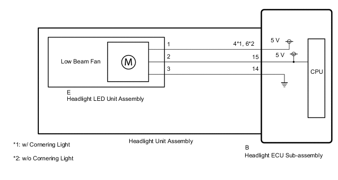
WIRING DIAGRAM
CAUTION / NOTICE / HINT
Note
After the headlight ECU sub-assembly LH is replaced, vehicle information registration and initialization are necessary.
PROCEDURE
-
CHECK FOR DTC
-
Clear the DTCs.
Body Electrical > HL AutoLeveling > Clear DTCs -
Check for DTCs.
Body Electrical > HL AutoLeveling > Trouble CodesOK DTC B243D or B243E output does not occur. Result Result Proceed to OK A NG (DTC B243D is output) B NG (DTC B243E is output) C
A 
USE SIMULATION METHOD TO CHECK Click here
C 
CHECK HEADLIGHT UNIT ASSEMBLY RH Click here
B 
-
-
CHECK HEADLIGHT UNIT ASSEMBLY LH
-
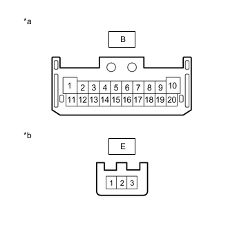
*a Component without harness connected
(to Headlight ECU Sub-assembly LH)
*b Component without harness connected
(to Headlight LED Unit Assembly LH)
Remove the headlight unit assembly LH.
for ALPHARD:
for VELLFIRE:
-
Measure the resistance according to the value(s) in the table below.
Standard Resistance w/ Cornering Light Tester Connection Condition Specified Condition B-4 - E-1 Always Below 1 Ω B-15 - E-2 Always Below 1 Ω B-14 - E-3 Always Below 1 Ω w/o Cornering Light Tester Connection Condition Specified Condition B-6 - E-1 Always Below 1 Ω B-15 - E-2 Always Below 1 Ω B-14 - E-3 Always Below 1 Ω Result Proceed to OK NG
NG
REPLACE HEADLIGHT UNIT ASSEMBLY LH for ALPHARD: REPLACE HEADLIGHT UNIT ASSEMBLY LH Click here
REPLACE HEADLIGHT UNIT ASSEMBLY LH for VELLFIRE: REPLACE HEADLIGHT UNIT ASSEMBLY LH Click hereOK
-
-
CHECK HEADLIGHT ECU SUB-ASSEMBLY LH
-
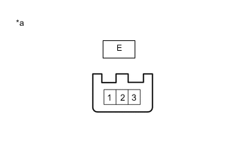
*a Component without harness connected
(to Headlight LED Unit Assembly LH)
Remove the headlight LED unit assembly LH.
for ALPHARD:
for VELLFIRE:
-
Connect the headlight ECU sub-assembly LH connectors.
-
Measure the voltage according to the value (s) in the table below.
Standard Voltage Tester Connection Condition Specified Condition E-1 - E-3 Low beam headlights illuminated 4.5 to 5.5 V E-2 - E-3 Low beam headlights illuminated 4.5 to 5.5 V Result Proceed to OK NG
OK
REPLACE HEADLIGHT LED UNIT ASSEMBLY LH for ALPHARD: REPLACE HEADLIGHT LED UNIT ASSEMBLY LH Click here
REPLACE HEADLIGHT LED UNIT ASSEMBLY LH for VELLFIRE: REPLACE HEADLIGHT LED UNIT ASSEMBLY LH Click hereNG
REPLACE HEADLIGHT ECU SUB-ASSEMBLY LH Click here
-
-
CHECK HEADLIGHT UNIT ASSEMBLY RH
-
*a Component without harness connected
(to Headlight ECU Sub-assembly RH)
*b Component without harness connected
(to Headlight LED Unit Assembly RH)
Remove the headlight unit assembly RH.
for ALPHARD:
for VELLFIRE:
-
Measure the resistance according to the value(s) in the table below.
Standard Resistance w/ Cornering Light Tester Connection Condition Specified Condition B-4 - E-1 Always Below 1 Ω B-15 - E-2 Always Below 1 Ω B-14 - E-3 Always Below 1 Ω w/o Cornering Light Tester Connection Condition Specified Condition B-6 - E-1 Always Below 1 Ω B-15 - E-2 Always Below 1 Ω B-14 - E-3 Always Below 1 Ω Result Proceed to OK NG
NG
REPLACE HEADLIGHT UNIT ASSEMBLY RH for ALPHARD: REPLACE HEADLIGHT UNIT ASSEMBLY RH Click here
REPLACE HEADLIGHT UNIT ASSEMBLY RH for VELLFIRE: REPLACE HEADLIGHT UNIT ASSEMBLY RH Click hereOK
-
-
CHECK HEADLIGHT UNIT ASSEMBLY RH
-
*a Component without harness connected
(to Headlight LED Unit Assembly RH)
Remove the headlight LED unit assembly RH.
for ALPHARD:
for VELLFIRE:
-
Connect the headlight ECU sub-assembly RH connectors.
-
Measure the voltage according to the value (s) in the table below.
Standard Voltage Tester Connection Condition Specified Condition E-1 - E-3 Low beam headlights illuminated 4.5 to 5.5 V E-2 - E-3 Low beam headlights illuminated 4.5 to 5.5 V Result Proceed to OK NG
OK
REPLACE HEADLIGHT LED UNIT ASSEMBLY RH for ALPHARD: REPLACE HEADLIGHT LED UNIT ASSEMBLY RH Click here
REPLACE HEADLIGHT LED UNIT ASSEMBLY RH for VELLFIRE: REPLACE HEADLIGHT LED UNIT ASSEMBLY RH Click hereNG
REPLACE HEADLIGHT ECU SUB-ASSEMBLY RH Click here
-