LIGHTING SYSTEM, Diagnostic DTC:B1244
| DTC Code | DTC Name |
|---|---|
| B1244 | Light Sensor Circuit Malfunction |
DESCRIPTION
The automatic light control sensor detects ambient light, converts it into an electrical signal and outputs it to the main body ECU (multiplex network body ECU). The main body ECU (multiplex network body ECU) turns the headlights and taillights on or off according to the signal.
The main body ECU (multiplex network body ECU) outputs DTC B1244.
| DTC No. | Detection Item | DTC Detection Condition | Trouble Area |
|---|---|---|---|
| B1244 | Light Sensor Circuit Malfunction |
|
|
WIRING DIAGRAM
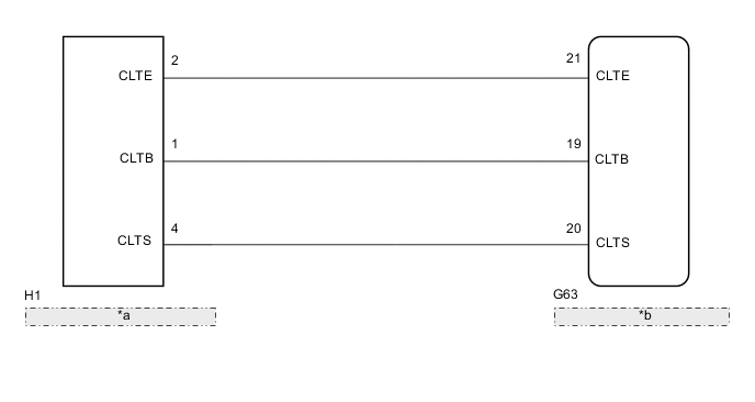
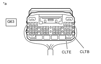
| *a | Automatic Light Control Sensor |
| *b | Main Body ECU (Multiplex Network Body ECU) |
CAUTION / NOTICE / HINT
Note
-
If the main body ECU (multiplex network body ECU) is replaced, refer to the Service Bulletin.
-
As the door control battery is installed between the vehicle battery and main body ECU (multiplex network body ECU), first perform the inspections in On-Vehicle Inspection to confirm that there are no malfunctions in the power source circuit for the main body ECU (multiplex network body ECU) before performing this troubleshooting procedure.
PROCEDURE
-
CLEAR DTC
-
Clear the DTCs.
Body Electrical > Main Body > Clear DTCsResult Proceed to NEXT
NEXT 
-
-
CHECK FOR DTC
-
Turn the engine switch on (IG).
-
Turn on the headlights using the headlight dimmer switch.
-
Check for DTCs.
Body Electrical > Main Body > Trouble CodesResult Proceed to DTC B1244 output does not occur DTC B1244 output occurs
DTC B1244 output does not occur 
USE SIMULATION METHOD TO CHECK Click here
DTC B1244 output occurs
-
-
READ VALUE USING GTS (LIGHT SENSOR ILLUMINANCE)
-
Using the GTS, read the Data List.
Body Electrical > Main Body > Data ListTester Display Measurement Item Range Normal Condition Diagnostic Note Light Sensor Illuminance Light control sensor illuminance 0 to 17600 lx Value is output according to ambient light level -
Body Electrical > Main Body > Data ListTester Display Light Sensor Illuminance OK The display is as specified in the normal condition column. Result Proceed to OK NG
OK
REPLACE MAIN BODY ECU (MULTIPLEX NETWORK BODY ECU) Click here
NG
-
-
CHECK HARNESS AND CONNECTOR (MAIN BODY ECU [MULTIPLEX NETWORK BODY ECU] - AUTOMATIC LIGHT CONTROL SENSOR)
-
Disconnect the G63 main body ECU (multiplex network body ECU) connector.
-
Disconnect the H1 automatic light control sensor connector.
-
Measure the resistance according to the value(s) in the table below.
Standard Resistance Tester Connection Condition Specified Condition G63-21 (CLTE) - H1-2 (CLTE) Always Below 1 Ω G63-19 (CLTB) - H1-1 (CLTB) Always Below 1 Ω G63-20 (CLTS) - H1-4 (CLTS) Always Below 1 Ω G63-21 (CLTE) - Body ground Always 10 kΩ or higher G63-19 (CLTB) - Body ground Always 10 kΩ or higher G63-20 (CLTS) - Body ground Always 10 kΩ or higher Result Proceed to OK NG
NG
REPAIR OR REPLACE HARNESS OR CONNECTOR
OK
-
-
CHECK MAIN BODY ECU (MULTIPLEX NETWORK BODY ECU)
-
*a Component with a harness connected
(Main Body ECU [Multiplex Network Body ECU])
Remove the junction block assembly LH and main body ECU (multiplex network body ECU) as a unit with the connectors still connected.
-
Measure the voltage according to the value(s) in the table below.
Standard Voltage Tester Connection Switch Condition Specified Condition G63-19 (CLTB) - G63-21 (CLTE) 1 minute has elapsed without operating any switches or opening or closing the doors after turning the engine switch off Below 1 V Engine switch on (IG), headlight dimmer switch in AUTO 11 to 14 V Result Proceed to OK NG
NG
REPLACE MAIN BODY ECU (MULTIPLEX NETWORK BODY ECU) Click here
OK
-
-
CHECK AUTOMATIC LIGHT CONTROL SENSOR
-
Check the automatic light control sensor.
Result Proceed to OK NG
OK
REPLACE MAIN BODY ECU (MULTIPLEX NETWORK BODY ECU) Click here
NG
REPLACE AUTOMATIC LIGHT CONTROL SENSOR Click here
-