LIGHTING SYSTEM Taillight Relay Circuit
DESCRIPTION
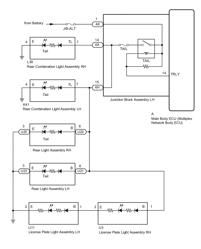
Illumination of the taillights and license plate light is controlled by the main body ECU (multiplex network body ECU).
WIRING DIAGRAM
CAUTION / NOTICE / HINT
Note
-
Inspect the fuses for circuits related to this system before performing the following procedure.
-
If the main body ECU (multiplex network body ECU) is replaced, refer to the Service Bulletin.
PROCEDURE
-
PERFORM ACTIVE TEST USING GTS
-
Using the GTS, perform the Active Test.
Body Electrical > Main Body > Active TestTester Display Measurement Item Control Range Diagnostic Note Taillight Relay Taillight relay ON or OFF -
Body Electrical > Main Body > Active TestTester Display Taillight Relay Result Result Proceed to Taillights and license lights come on A Taillights and license lights do not come on B
A 
PROCEED TO NEXT SUSPECTED AREA SHOWN IN PROBLEM SYMPTOMS TABLE Click here
B 
-
-
CHECK HARNESS AND CONNECTOR (JUNCTION BLOCK ASSEMBLY LH - BATTERY)
-
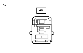
*a Front view of wire harness connector
(to Junction Block Assembly LH)
Disconnect the junction block assembly LH connector.
-
Measure the voltage according to the value(s) in the table below.
Standard Voltage Tester Connection Condition Specified Condition 4K-1 - Body ground Always 11 to 14 V Result Proceed to OK NG
NG
REPAIR OR REPLACE HARNESS OR CONNECTOR
OK
-
-
INSPECT JUNCTION BLOCK ASSEMBLY LH
-
Remove the junction block assembly LH.
-
Remove the main body ECU (multiplex network body ECU) from the junction block assembly LH.
-
Measure the resistance according to the value(s) in the table below.
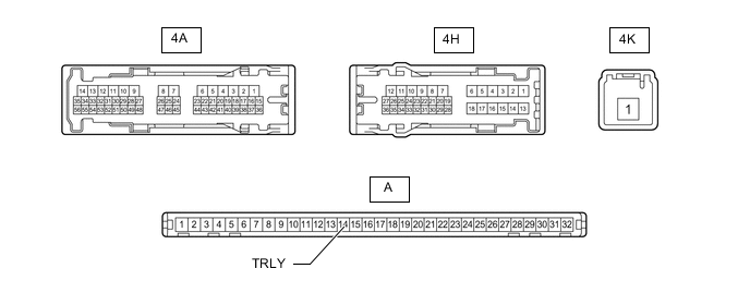
Standard Resistance Tester Connection Condition Specified Condition 4K-1 - 4H-15 Always 10 kΩ or higher -
Measure the voltage according to the value(s) in the table below.
Standard Voltage Tester Connection Condition Specified Condition 4A-14 - Battery negative (-) terminal Battery voltage applied between terminals 4K-1 and A-14 (TRLY) 11 to 14 V Battery voltage not applied between terminals 4K-1 and A-14 (TRLY) Below 1 V 4H-15 - Battery negative (-) terminal Battery voltage applied between terminals 4K-1 and A-14 (TRLY) 11 to 14 V Battery voltage not applied between terminals 4K-1 and A-14 (TRLY) Below 1 V Result Proceed to OK NG
OK
REPLACE MAIN BODY ECU (MULTIPLEX NETWORK BODY ECU) Click here
NG
REPLACE JUNCTION BLOCK ASSEMBLY LH Click here
-