OUTER REAR VIEW MIRROR REASSEMBLY
CAUTION / NOTICE / HINT
Tech Tips
-
Use the same procedure for the RH and LH sides.
-
The procedure listed below is for the LH side.
PROCEDURE
-
INSTALL OUTER MIRROR RETRACTOR LH (w/o Memory, w/ Panoramic View Monitor System)
-
Install the frame sub-assembly.
-

Install in this Direction Install a new frame sub-assembly to a new support.
-
-
Install the support.
-
Install the support and frame sub-assembly with 3 new screws.
-
-
Install the actuator sub-assembly.
-
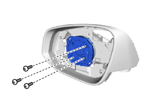
Install the actuator sub-assembly with the 3 screws.
-
-
Install the hook.
-
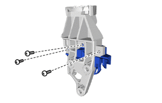
Install a new hook to the base sub-assembly with 3 new screws.
-
-
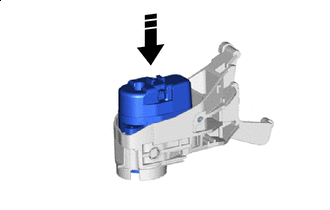
Install the upper cover sub-assembly.
-
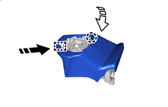
Install in this Direction (1) 
Install in this Direction (2) Attach the guide and install a new upper cover sub-assembly to the base sub-assembly.
-
Attach the claw.
-
-
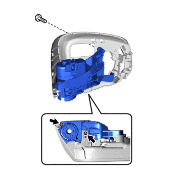
Install the base sub-assembly.
-
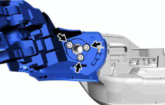
Using a T25 "TORX" socket wrench, install the base sub-assembly with 3 new "TORX" screws.
- Torque:
- 3.4 N*m { 35 kgf*cm, 30 in.*lbf }
-
-
Install the harness sub-assembly.
-
Install in this Direction Pull a new harness sub-assembly through the frame sub-assembly as shown in the illustration.
-
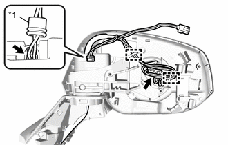
*1 Rubber Cover Connect the connector and attach the rubber cover.
-
Connect the actuator sub-assembly connector and attach the clamp.
-
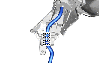
Attach the clamp.
-
-
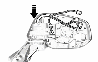
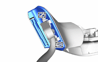
Install the lower cover.
-
Attach the claw and install a new lower cover.
-
-
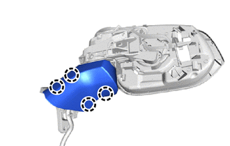
Install the gasket.
-
Attach the guide and install a new gasket.
-
-
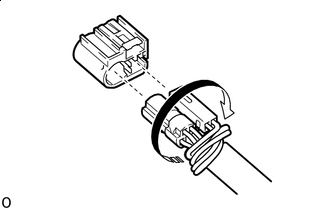
*a Twist Rotate in this Direction w/o Memory:
-
Connect each connector to a new adapter.
-
-
Rotate the adapter and twist the longer wire harness as shown in the illustration.
-
Assemble the connector.(w/ Multi-terrain Monitor)
-
Move the retainer to the unlock position.
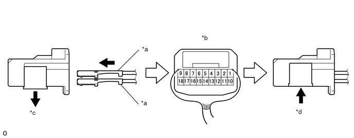
*a Wire Harness Pin *b Rear View of Connector *c Retainer Unlock Position *d Retainer Lock Position -
Insert the pins of the wire harness sub-assembly into the back of connector until they lock.
Wire Harness Color Chart 1 2 3 4 5 6 7 8 9 Purple Light Green Sky Blue pink Black/Green Yellow/Black Green Blue - 10 11 12 13 14 15 16 17 18 Brown Red White Green/Red Orange White/Black Gray Black Yellow -
Move the retainer to the lock position.
Note
-
When inserting the pins of the wire harness, compare the new connector with the connector that was cut off during removal and make sure that the arrangement of the wire colors of the pins is the same as before.
-
Confirm that the pins of the wire harness are securely locked and cannot be pulled out.
-
When a pin of the wire harness is locked, it cannot be pulled out. Therefore, be sure to insert each pin into the correct location.
-
-
-
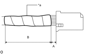
*a Vinyl Tape Wrap new vinyl tape as shown in the illustration.
Standard Clearance Area Measurement A Below 10 mm (0.39 in.) B 55 mm (2.17 in.) Note
Wrap the vinyl tape tightly around the wire harness to ensure that there are no gaps.
-
-
INSTALL SIDE TELEVISION CAMERA ASSEMBLY LH
-
INSTALL SIDE TURN SIGNAL LIGHT ASSEMBLY LH
-
INSTALL OUTER MIRROR COVER LH
-
INSTALL OUTER MIRROR LH