OUTER REAR VIEW MIRROR REASSEMBLY
CAUTION / NOTICE / HINT
Tech Tips
-
Use the same procedure for the RH and LH sides.
-
The procedure listed below is for the LH side.
PROCEDURE
-
INSTALL OUTER MIRROR RETRACTOR LH
-
Install the frame sub-assembly.
-

Install in this Direction Install a new frame sub-assembly to a new support.
-
-
Install the support.
-
Install the support and frame sub-assembly with 3 new screws.
-
-
Install the actuator sub-assembly.
-
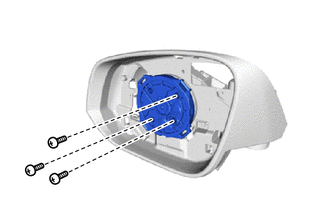
Install the actuator sub-assembly with the 3 screws.
-
-
Install the hook.
-
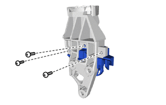
Install a new hook to the base with 3 new screws.
-
-
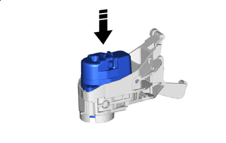
Install the upper cover sub-assembly.
-
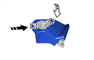
Install in this Direction (1) 
Install in this Direction (2) Attach the guide and install a new upper cover sub-assembly to the base.
-
Attach the claw.
-
-
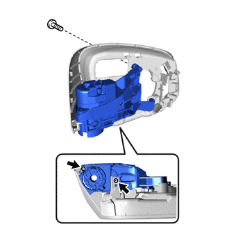
Install the base sub-assembly.
-
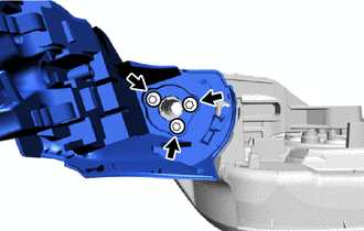
Using a T25 "TORX" socket wrench, install the base sub-assembly with 3 new "TORX" screws.
- Torque:
- 3.4 N*m { 35 kgf*cm, 30 in.*lbf }
-
-
Install the harness sub-assembly.
-
Install in this Direction Pull a new harness sub-assembly through the frame sub-assembly as shown in the illustration.
-
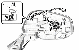
*1 Rubber Cover Connect the connector and attach the rubber cover.
-
Connect the actuator sub-assembly connector and attach the clamp.
-
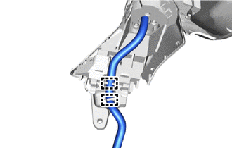
Attach the clamp.
-
-
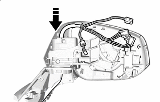
Install the lower cover.
-
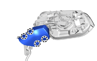
Attach the claw and install a new lower cover.
-
-
Install the gasket.
-
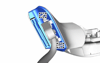
Attach the guide and install a new gasket.
-
-
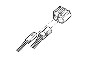
Connect each connector to a new adapter.
-
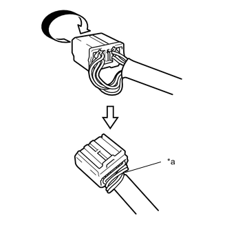
*a Twist 
Rotate in this Direction Rotate the adapter and twist the longer wire harness as shown in the illustration.
-
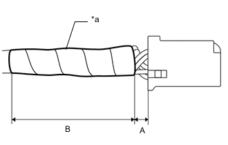
*a Vinyl Tape Wrap new vinyl tape as shown in the illustration.
Standard Clearance Area Measurement A Below 10 mm (0.3937 in.) B 55 mm (2.1654 in.) Note
Wrap the vinyl tape tightly around the wire harness to ensure that there are no gaps.
-
-
INSTALL SIDE TELEVISION CAMERA ASSEMBLY LH
-
INSTALL SIDE TURN SIGNAL LIGHT ASSEMBLY LH
-
INSTALL OUTER MIRROR COVER LH
-
INSTALL OUTER MIRROR LH