OUTER REAR VIEW MIRROR INSPECTION
PROCEDURE
-
INSPECT OUTER REAR VIEW MIRROR ASSEMBLY LH (w/o Memory)
-
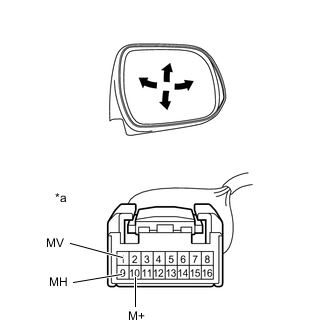
Check the operation of the mirror surface.
-
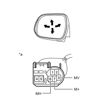
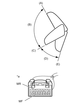
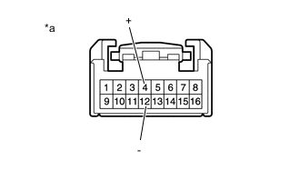
*a Component without harness connected
(Outer Rear View Mirror Assembly LH)
Disconnect the outer rear view mirror assembly LH connector.
-
Apply battery voltage and check the operation of the mirror.
OK Tester Connection Specified Condition Battery positive (+) → 3 (MV)
Battery negative (-) → 7 (M+)
Turns upward Battery positive (+) → 7 (M+)
Battery negative (-) → 3 (MV)
Turns downward Battery positive (+) → 7 (M+)
Battery negative (-) → 6 (MH)
Turns right Battery positive (+) → 6 (MH)
Battery negative (-) → 7 (M+)
Turns left If the result is not as specified, replace the outer mirror retractor LH.
-
-
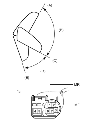
Check the operation of the retractable mirror.
Note
-
Disconnect and reconnect the battery between each mirror position check.
-
The mirror position cannot be changed manually when the battery is connected. To change the mirror position manually, the battery must be disconnected first.
-
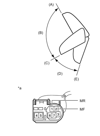
*a Component without harness connected
(Outer Rear View Mirror Assembly LH)
Disconnect the outer rear view mirror assembly LH connector.
-
For each position: Disconnect the battery, set the mirror position by hand, connect the battery, and check the retractable mirror movement.
OK Tester Connection mirror Position Specified Condition Battery positive (+) → 1 (MR)
Battery negative (-) → 2 (MF)
Forward position (A) Moves from (A) to (E) Battery positive (+) → 2 (MF)
Battery negative (-) → 1 (MR)
Forward position (A) Does not move Battery positive (+) → 1 (MR)
Battery negative (-) → 2 (MF)
Position (B) Moves from (B) to (E) Battery positive (+) → 2 (MF)
Battery negative (-) → 1 (MR)
Position (B) Moves from (B) to (A) Battery positive (+) → 1 (MR)
Battery negative (-) → 2 (MF)
Driving position (C) Moves from (C) to (E) Battery positive (+) → 2 (MF)
Battery negative (-) → 1 (MR)
Driving position (C) Does not move Battery positive (+) → 1 (MR)
Battery negative (-) → 2 (MF)
Position (D) Moves from (D) to (E) Battery positive (+) → 2 (MF)
Battery negative (-) → 1 (MR)
Position (D) Moves from (D) to (C) Battery positive (+) → 1 (MR)
Battery negative (-) → 2 (MF)
Retracted position (E) Does not move Battery positive (+) → 2 (MF)
Battery negative (-) → 1 (MR)
Retracted position (E) Moves from (E) to (C) If the result is not as specified, replace the outer mirror retractor LH.
-
-
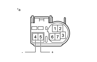
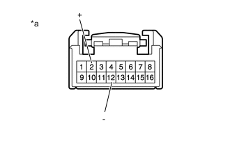
*a Component without harness connected
(Outer Rear View Mirror Assembly LH)
Check the side turn signal light assembly LH.
-
Disconnect the outer rear view mirror assembly LH connector.
-
Apply battery voltage to the terminals of the connector, and check the illumination condition.
OK Tester Connection Specified Condition Battery positive (+) → 5 (+)
Battery negative (-) → 4 (-)
Side turn light illuminates If the result is not as specified, inspect the side turn signal light assembly LH or replace the outer mirror retractor LH.
-
-
-
INSPECT OUTER REAR VIEW MIRROR ASSEMBLY LH (w/ Memory)
-
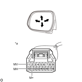
Check the operation of the mirror surface.
-
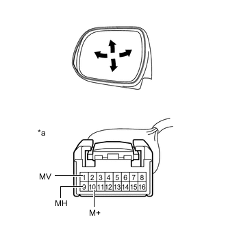
*a Component without harness connected
(Outer Rear View Mirror Assembly LH)
Disconnect the outer rear view mirror assembly LH connector.
-
Apply battery voltage and check the operation of the mirror.
OK Tester Connection Specified Condition Battery positive (+) → 1 (MV)
Battery negative (-) → 10 (M+)
Turns upward Battery positive (+) → 10 (M+)
Battery negative (-) → 1 (MV)
Turns downward Battery positive (+) → 10 (M+)
Battery negative (-) → 9 (MH)
Turns right Battery positive (+) → 9 (MH)
Battery negative (-) → 10 (M+)
Turns left If the result is not as specified, replace the outer rear view mirror assembly LH.
-
-
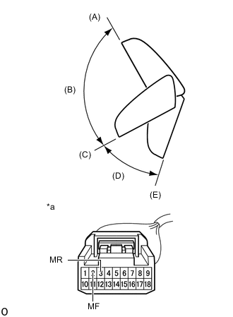
Check the operation of the retractable mirror.
Note
-
Disconnect and reconnect the battery between each mirror position check.
-
The mirror position cannot be changed manually when the battery is connected. To change the mirror position manually, the battery must be disconnected first.
-
*a Component without harness connected
(Outer Rear View Mirror Assembly LH)
Disconnect the outer rear view mirror assembly LH connector.
-
For each position: Disconnect the battery, set the mirror position by hand, connect the battery, and check the retractable mirror movement.
OK Tester Connection Condition Specified Condition Battery positive (+) → 3 (MR)
Battery negative (-) → 11 (MF)
Forward position (A) Moves from (A) to (E) Battery positive (+) → 11 (MF)
Battery negative (-) → 3 (MR)
Forward position (A) Does not move Battery positive (+) → 3 (MR)
Battery negative (-) → 11 (MF)
Position (B) Moves from (B) to (E) Battery positive (+) → 11 (MF)
Battery negative (-) → 3 (MR)
Position (B) Moves from (B) to (A) Battery positive (+) → 3 (MR)
Battery negative (-) → 11 (MF)
Driving position (C) Moves from (C) to (E) Battery positive (+) → 11 (MF)
Battery negative (-) → 3 (MR)
Driving position (C) Does not move Battery positive (+) → 3 (MR)
Battery negative (-) → 11 (MF)
Position (D) Moves from (D) to (E) Battery positive (+) → 11 (MF)
Battery negative (-) → 3 (MR)
Position (D) Moves from (D) to (C) Battery positive (+) → 3 (MR)
Battery negative (-) → 11 (MF)
Retracted position (E) Does not move Battery positive (+) → 11 (MF)
Battery negative (-) → 3 (MR)
Retracted position (E) Moves from (E) to (C) If the result is not as specified, replace the outer rear view mirror assembly LH.
-
-
*a Component without harness connected
(Outer Rear View Mirror Assembly LH)
Check the side turn signal light assembly LH.
-
Disconnect the outer rear view mirror assembly LH connector.
-
Apply battery voltage to the terminals of the connector, and check the illumination condition.
OK Tester Connection Specified Condition Battery positive (+) → 4 (+)
Battery negative (-) → 12 (-)
Side turn light illuminates If the result is not as specified, inspect the side turn signal light assembly LH or replace the outer rear view mirror assembly LH.
-
-
w/ Mirror Heater:
Check the operation of the mirror heater.
-
*a Component without harness connected
(Outer Rear View Mirror Assembly LH)
Disconnect the outer rear view mirror assembly LH connector.
-
Measure the resistance according to the value(s) in the table below.
Standard Resistance Tester Connection Condition Specified Condition 2 (+) - 12 (-) 25°C (75°F) 7.1 to 9.5 Ω If the result is not as specified, inspect the outer mirror LH or replace the outer rear view mirror assembly LH.
-
-
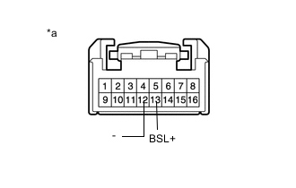
*a Component without harness connected
(Outer Rear View Mirror Assembly LH)
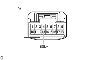
w/ Blind Spot Monitor System:
Check the operation of the blind spot monitor indicator.
-
Connect 4 new 1.5 V dry-cell batteries in series.
-
Apply 6 V dry-cell batteries to the terminals of the connector, and check the blind spot monitor indicator condition.
OK Battery Connection Specified Condition 6 V Battery Positive (+) → 13 (BSL+)
6 V Battery Negative (-) → 12 (-)
Blind spot monitor indicator comes on If the result is not as specified, inspect the outer mirror LH or replace the outer rear view mirror assembly LH.
-
-
-
INSPECT OUTER REAR VIEW MIRROR ASSEMBLY LH (w/ Panoramic View Monitor System)
-
Check the operation of the mirror surface.
-
*a Component without harness connected
(Outer Rear View Mirror Assembly LH)
Disconnect the outer rear view mirror assembly LH connector.
-
Apply battery voltage and check the operation of the mirror.
OK Tester Connection Specified Condition Battery positive (+) → 1 (MV)
Battery negative (-) → 11 (M+)
Turns upward Battery positive (+) → 11 (M+)
Battery negative (-) → 1 (MV)
Turns downward Battery positive (+) → 11 (M+)
Battery negative (-) → 10 (MH)
Turns right Battery positive (+) → 10 (MH)
Battery negative (-) → 11 (M+)
Turns left If the result is not as specified, replace the outer mirror retractor LH.
-
-
Check the operation of the retractable mirror.
Note
-
Disconnect and reconnect the battery between each mirror position check.
-
The mirror position cannot be changed manually when the battery is connected. To change the mirror position manually, the battery must be disconnected first.
-
*a Component without harness connected
(Outer Rear View Mirror Assembly LH)
Disconnect the outer rear view mirror assembly LH connector.
-
For each position: Disconnect the battery, set the mirror position by hand, connect the battery, and check the retractable mirror movement.
OK Tester Connection Condition Specified Condition Battery positive (+) → 3 (MR)
Battery negative (-) → 2 (MF)
Forward position (A) Moves from (A) to (E) Battery positive (+) → 2 (MF)
Battery negative (-) → 3 (MR)
Forward position (A) Does not move Battery positive (+) → 3 (MR)
Battery negative (-) → 2 (MF)
Position (B) Moves from (B) to (E) Battery positive (+) → 2 (MF)
Battery negative (-) → 3 (MR)
Position (B) Moves from (B) to (A) Battery positive (+) → 3 (MR)
Battery negative (-) → 2 (MF)
Driving position (C) Moves from (C) to (E) Battery positive (+) → 2 (MF)
Battery negative (-) → 3 (MR)
Driving position (C) Does not move Battery positive (+) → 3 (MR)
Battery negative (-) → 2 (MF)
Position (D) Moves from (D) to (E) Battery positive (+) → 2 (MF)
Battery negative (-) → 3 (MR)
Position (D) Moves from (D) to (C) Battery positive (+) → 3 (MR)
Battery negative (-) → 2 (MF)
Retracted position (E) Does not move Battery positive (+) → 2 (MF)
Battery negative (-) → 3 (MR)
Retracted position (E) Moves from (E) to (C) If the result is not as specified, replace the outer mirror retractor LH.
-
-

*a Component without harness connected
(Outer Rear View Mirror Assembly LH)
Check the side turn signal light assembly LH.
-
Disconnect the outer rear view mirror assembly LH connector.
-
Apply battery voltage to the terminals of the connector, and check the illumination condition.
OK Tester Connection Specified Condition Battery positive (+) → 4 (+)
Battery negative (-) → 12 (-)
Side turn light illuminates If the result is not as specified, inspect the side turn signal light assembly LH or replace the outer mirror retractor LH.
-
-
w/ Mirror Heater:
Check the operation of the mirror heater.
-

*a Component without harness connected
(Outer Rear View Mirror Assembly LH)
Disconnect the outer rear view mirror assembly LH connector.
-
Measure the resistance according to the value(s) in the table below.
Standard Resistance Tester Connection Condition Specified Condition 5 (+) - 12 (-) 25°C (75°F) 7.1 to 9.5 Ω If the result is not as specified, inspect the outer mirror LH or replace the outer mirror retractor LH.
-
-
*a Component without harness connected
(Outer Rear View Mirror Assembly LH)
w/ Blind Spot Monitor System:
Check the operation of the blind spot monitor indicator.
-
Connect 4 new 1.5 V dry-cell batteries in series.
-
Apply 6 V dry-cell batteries to the terminals of the connector, and check the blind spot monitor indicator condition.
OK Battery Connection Specified Condition 6 V Battery Positive (+) → 13 (BSL+)
6 V Battery Negative (-) → 12 (-)
Blind spot monitor indicator comes on If the result is not as specified, inspect the outer mirror LH or replace the outer mirror retractor LH.
-
-
-
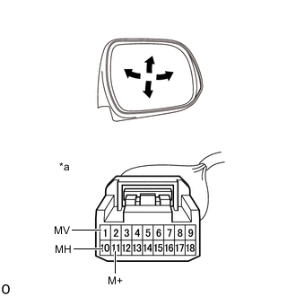
INSPECT OUTER REAR VIEW MIRROR ASSEMBLY RH (w/o Memory)
-
Check the operation of the mirror surface.
-
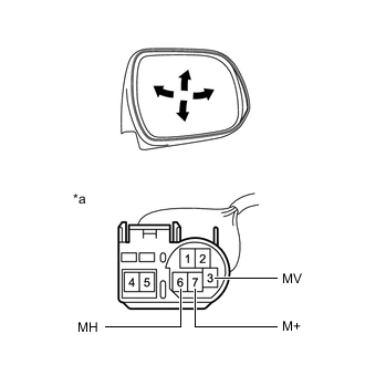
*a Component without harness connected
(Outer Rear View Mirror Assembly RH)
Disconnect the outer rear view mirror assembly RH connector.
-
Apply battery voltage and check the operation of the mirror.
OK Tester Connection Specified Condition Battery positive (+) → 3 (MV)
Battery negative (-) → 7 (M+)
Turns upward Battery positive (+) → 7 (M+)
Battery negative (-) → 3 (MV)
Turns downward Battery positive (+) → 6 (MH)
Battery negative (-) → 7 (M+)
Turns left Battery positive (+) → 7 (M+)
Battery negative (-) → 6 (MH)
Turns right If the result is not as specified, replace the outer mirror retractor RH.
-
-
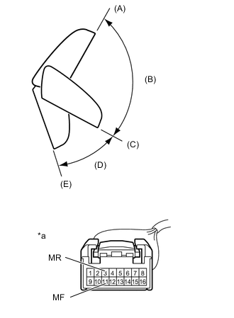
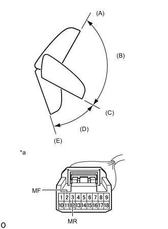
Check the operation of the retractable mirror.
Note
-
Disconnect and reconnect the battery between each mirror position check.
-
The mirror position cannot be changed manually when the battery is connected. To change the mirror position manually, the battery must be disconnected first.
-
*a Component without harness connected
(Outer Rear View Mirror Assembly RH)
Disconnect the outer rear view mirror assembly RH connector.
-
For each position: Disconnect the battery, set the mirror position by hand, connect the battery, and check the retractable mirror movement.
OK Tester Connection mirror Position Specified Condition Battery positive (+) → 1 (MR)
Battery negative (-) → 2 (MF)
Forward position (A) Moves from (A) to (E) Battery positive (+) → 2 (MF)
Battery negative (-) → 1 (MR)
Forward position (A) Does not move Battery positive (+) → 1 (MR)
Battery negative (-) → 2 (MF)
Position (B) Moves from (B) to (E) Battery positive (+) → 2 (MF)
Battery negative (-) → 1 (MR)
Position (B) Moves from (B) to (A) Battery positive (+) → 1 (MR)
Battery negative (-) → 2 (MF)
Driving position (C) Moves from (C) to (E) Battery positive (+) → 2 (MF)
Battery negative (-) → 1 (MR)
Driving position (C) Does not move Battery positive (+) → 1 (MR)
Battery negative (-) → 2 (MF)
Position (D) Moves from (D) to (E) Battery positive (+) → 2 (MF)
Battery negative (-) → 1 (MR)
Position (D) Moves from (D) to (C) Battery positive (+) → 1 (MR)
Battery negative (-) → 2 (MF)
Retracted position (E) Does not move Battery positive (+) → 2 (MF)
Battery negative (-) → 1 (MR)
Retracted position (E) Moves from (E) to (C) If the result is not as specified, replace the outer mirror retractor RH.
-
-
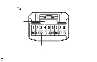
*a Component without harness connected
(Outer Rear View Mirror Assembly RH)
Check the side turn signal light assembly RH.
-
Disconnect the outer rear view mirror assembly RH connector.
-
Apply battery voltage to the terminals of the connector, and check the illumination condition.
OK Tester Connection Specified Condition Battery positive (+) → 5 (+)
Battery negative (-) → 4 (-)
Side turn light illuminates If the result is not as specified, inspect the side turn signal light assembly RH or replace the outer mirror retractor RH.
-
-
-
INSPECT OUTER REAR VIEW MIRROR ASSEMBLY RH (w/ Memory)
-
Check the operation of the mirror surface.
-
*a Component without harness connected
(Outer Rear View Mirror Assembly RH)
Disconnect the outer rear view mirror assembly RH connector.
-
Apply battery voltage and check the operation of the mirror.
OK Tester Connection Specified Condition Battery positive (+) → 1 (MV)
Battery negative (-) → 10 (M+)
Turns upward Battery positive (+) → 10 (M+)
Battery negative (-) → 1 (MV)
Turns downward Battery positive (+) → 9 (MH)
Battery negative (-) → 10 (M+)
Turns left Battery positive (+) → 10 (M+)
Battery negative (-) → 9 (MH)
Turns right If the result is not as specified, replace the outer rear view mirror assembly RH.
-
-
Check the operation of the retractable mirror.
Note
-
Disconnect and reconnect the battery between each mirror position check.
-
The mirror position cannot be changed manually when the battery is connected. To change the mirror position manually, the battery must be disconnected first.
-
*a Component without harness connected
(Outer Rear View Mirror Assembly RH)
Disconnect the outer rear view mirror assembly RH connector.
-
For each position: Disconnect the battery, set the mirror position by hand, connect the battery, and check the retractable mirror movement.
OK Tester Connection Condition Specified Condition Battery positive (+) → 3 (MR)
Battery negative (-) → 11 (MF)
Forward position (A) Moves from (A) to (E) Battery positive (+) → 11 (MF)
Battery negative (-) → 3 (MR)
Forward position (A) Does not move Battery positive (+) → 3 (MR)
Battery negative (-) → 11 (MF)
Position (B) Moves from (B) to (E) Battery positive (+) → 11 (MF)
Battery negative (-) → 3 (MR)
Position (B) Moves from (B) to (A) Battery positive (+) → 3 (MR)
Battery negative (-) → 11 (MF)
Driving position (C) Moves from (C) to (E) Battery positive (+) → 11 (MF)
Battery negative (-) → 3 (MR)
Driving position (C) Does not move Battery positive (+) → 3 (MR)
Battery negative (-) → 11 (MF)
Position (D) Moves from (D) to (E) Battery positive (+) → 11 (MF)
Battery negative (-) → 3 (MR)
Position (D) Moves from (D) to (C) Battery positive (+) → 3 (MR)
Battery negative (-) → 11 (MF)
Retracted position (E) Does not move Battery positive (+) → 11 (MF)
Battery negative (-) → 3 (MR)
Retracted position (E) Moves from (E) to (C) If the result is not as specified, replace the outer rear view mirror assembly RH.
-
-

*a Component without harness connected
(Outer Rear View Mirror Assembly RH)
Check the side turn signal light assembly RH.
-
Disconnect the outer rear view mirror assembly RH connector.
-
Apply battery voltage to the terminals of the connector, and check the illumination condition.
OK Tester Connection Specified Condition Battery positive (+) → 4 (+)
Battery negative (-) → 12 (-)
Side turn light illuminates If the result is not as specified, inspect the side turn signal light assembly RH or replace the outer rear view mirror assembly RH.
-
-
w/ Mirror Heater:
Check the operation of the mirror heater.
-

*a Component without harness connected
(Outer Rear View Mirror Assembly RH)
Disconnect the outer rear view mirror assembly RH connector.
-
Measure the resistance according to the value(s) in the table below.
Standard Resistance Tester Connection Condition Specified Condition 2 (+) - 12 (-) 25°C (75°F) 7.1 to 9.5 Ω If the result is not as specified, inspect the outer mirror RH or replace the outer rear view mirror assembly RH.
-
-
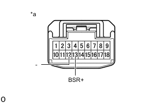
*a Component without harness connected
(Outer Rear View Mirror Assembly RH)
w/ Blind Spot Monitor System:
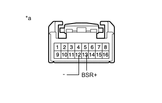
Check the operation of the blind spot monitor indicator.
-
Connect 4 new 1.5 V dry-cell batteries in series.
-
Apply 6 V dry-cell batteries to the terminals of the connector, and check the blind spot monitor indicator condition.
OK Battery Connection Specified Condition 6 V Battery Positive (+) → 13 (BSR+)
6 V Battery Negative (-) → 12 (-)
Blind spot monitor indicator comes on If the result is not as specified, inspect the outer mirror RH or replace the outer rear view mirror assembly RH.
-
-
-
INSPECT OUTER REAR VIEW MIRROR ASSEMBLY RH (w/ Panoramic View Monitor System)
-
Check the operation of the mirror surface.
-
*a Component without harness connected
(Outer Rear View Mirror Assembly RH)
Disconnect the outer rear view mirror assembly RH connector.
-
Apply battery voltage and check the operation of the mirror.
OK Tester Connection Specified Condition Battery positive (+) → 1 (MV)
Battery negative (-) → 11 (M+)
Turns upward Battery positive (+) → 11 (M+)
Battery negative (-) → 1 (MV)
Turns downward Battery positive (+) → 11 (MH)
Battery negative (-) → 10 (M+)
Turns left Battery positive (+) → 10 (M+)
Battery negative (-) → 11 (MH)
Turns right If the result is not as specified, replace the outer mirror retractor RH.
-
-
Check the operation of the retractable mirror.
Note
-
Disconnect and reconnect the battery between each mirror position check.
-
The mirror position cannot be changed manually when the battery is connected. To change the mirror position manually, the battery must be disconnected first.
-
*a Component without harness connected
(Outer Rear View Mirror Assembly RH)
Disconnect the outer rear view mirror assembly RH connector.
-
For each position: Disconnect the battery, set the mirror position by hand, connect the battery, and check the retractable mirror movement.
OK Tester Connection Condition Specified Condition Battery positive (+) → 3 (MR)
Battery negative (-) → 2 (MF)
Forward position (A) Moves from (A) to (E) Battery positive (+) → 2 (MF)
Battery negative (-) → 3 (MR)
Forward position (A) Does not move Battery positive (+) → 3 (MR)
Battery negative (-) → 2 (MF)
Position (B) Moves from (B) to (E) Battery positive (+) → 2 (MF)
Battery negative (-) → 3 (MR)
Position (B) Moves from (B) to (A) Battery positive (+) → 3 (MR)
Battery negative (-) → 2 (MF)
Driving position (C) Moves from (C) to (E) Battery positive (+) → 2 (MF)
Battery negative (-) → 3 (MR)
Driving position (C) Does not move Battery positive (+) → 3 (MR)
Battery negative (-) → 2 (MF)
Position (D) Moves from (D) to (E) Battery positive (+) → 2 (MF)
Battery negative (-) → 3 (MR)
Position (D) Moves from (D) to (C) Battery positive (+) → 3 (MR)
Battery negative (-) → 2 (MF)
Retracted position (E) Does not move Battery positive (+) → 2 (MF)
Battery negative (-) → 3 (MR)
Retracted position (E) Moves from (E) to (C) If the result is not as specified, replace the outer mirror retractor RH.
-
-
*a Component without harness connected
(Outer Rear View Mirror Assembly RH)
Check the side turn signal light assembly RH.
-
Disconnect the outer rear view mirror assembly RH connector.
-
Apply battery voltage to the terminals of the connector, and check the illumination condition.
OK Tester Connection Specified Condition Battery positive (+) → 4 (+)
Battery negative (-) → 12 (-)
Side turn light illuminates If the result is not as specified, inspect the side turn signal light assembly RH or replace the outer mirror retractor RH.
-
-
w/ Mirror Heater:
Check the operation of the mirror heater.
-

*a Component without harness connected
(Outer Rear View Mirror Assembly RH)
Disconnect the outer rear view mirror assembly RH connector.
-
Measure the resistance according to the value(s) in the table below.
Standard Resistance Tester Connection Condition Specified Condition 5 (+) - 12 (-) 25°C (75°F) 7.1 to 9.5 Ω If the result is not as specified, inspect the outer mirror RH or replace the outer mirror retractor RH.
-
-
*a Component without harness connected
(Outer Rear View Mirror Assembly RH)
w/ Blind Spot Monitor System:
Check the operation of the blind spot monitor indicator.
-
Connect 4 new 1.5 V dry-cell batteries in series.
-
Apply 6 V dry-cell batteries to the terminals of the connector, and check the blind spot monitor indicator condition.
OK Battery Connection Specified Condition 6 V Battery Negative (-) → 13 (BSR+)
6 V Battery Negative (-) → 12 (-)
Blind spot monitor indicator comes on If the result is not as specified, replace the outer rear view mirror assembly RH.
-
-