OUTER REAR VIEW MIRROR DISASSEMBLY
CAUTION / NOTICE / HINT
Tech Tips
-
Use the same procedure for the RH and LH sides.
-
The procedure listed below is for the LH side.
PROCEDURE
-
REMOVE OUTER MIRROR LH
-
REMOVE OUTER MIRROR COVER LH
-
REMOVE SIDE TURN SIGNAL LIGHT ASSEMBLY LH
-
REMOVE SIDE TELEVISION CAMERA ASSEMBLY LH (w/ Panoramic View Monitor System)
-
REMOVE OUTER MIRROR RETRACTOR LH (w/o Memory)
-
Remove the gasket.
-
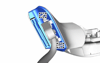
Detach the guide and remove the gasket.
-
-
Remove the lower cover.
-
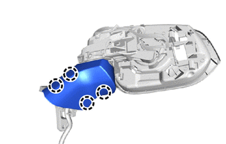
Detach the claw and remove the lower cover.
-
-
Remove the harness sub-assembly.
-
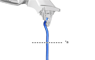
*a Cut here Cut the harness sub-assembly at the location shown in the illustration.
Tech Tips
A new harness sub-assembly is used for reassembly.
-
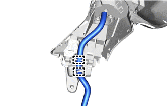
Detach the clamp.
-
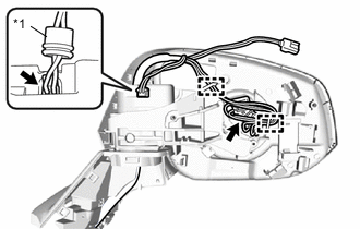
*1 Rubber Cover Detach the clamp and disconnect the actuator sub-assembly connector.
-
Detach the rubber cover and disconnect the connector.
-
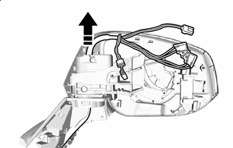

Remove in this Direction Pull out the harness sub-assembly as shown in the illustration.
-
-
Remove the base sub-assembly.
-
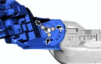
Using a T25 "TORX" socket wrench, remove the 3 "TORX" screws and base sub-assembly.
-
-
Remove the upper cover sub-assembly.
-
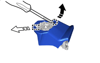

Protective Tape Remove in this Direction (1) 
Remove in this Direction (2) Using a screwdriver, detach the claw as shown in the illustration.
Tech Tips
Tape the screwdriver tip before use.
-
Detach the guide and remove the upper cover sub-assembly from the base.
-
-
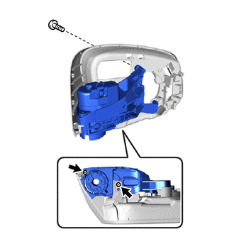
Remove the hook.
-
Remove the 3 screws and hook from the base.
-
-
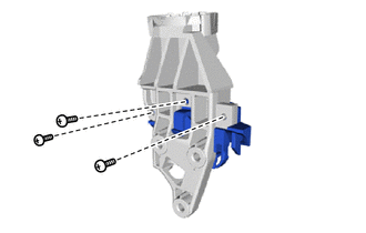
Remove the actuator sub-assembly.
-
Remove the 3 screws and actuator sub-assembly.
-
-
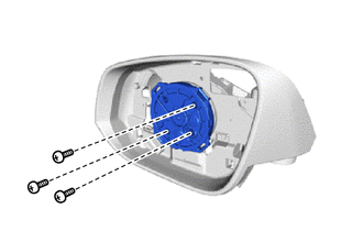
Remove the support.
-
Remove the 3 screws and the support and frame sub-assembly.
-
-
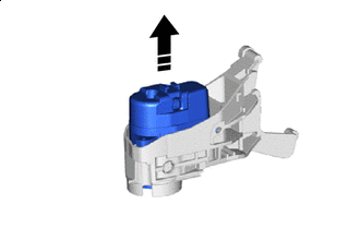
Remove in this Direction Remove the frame sub-assembly.
-
Remove the frame sub-assembly from the support.
-
-