POWER MIRROR CONTROL SYSTEM(w/o Memory) AUTO Power Retract Mirrors do not operate
DESCRIPTION
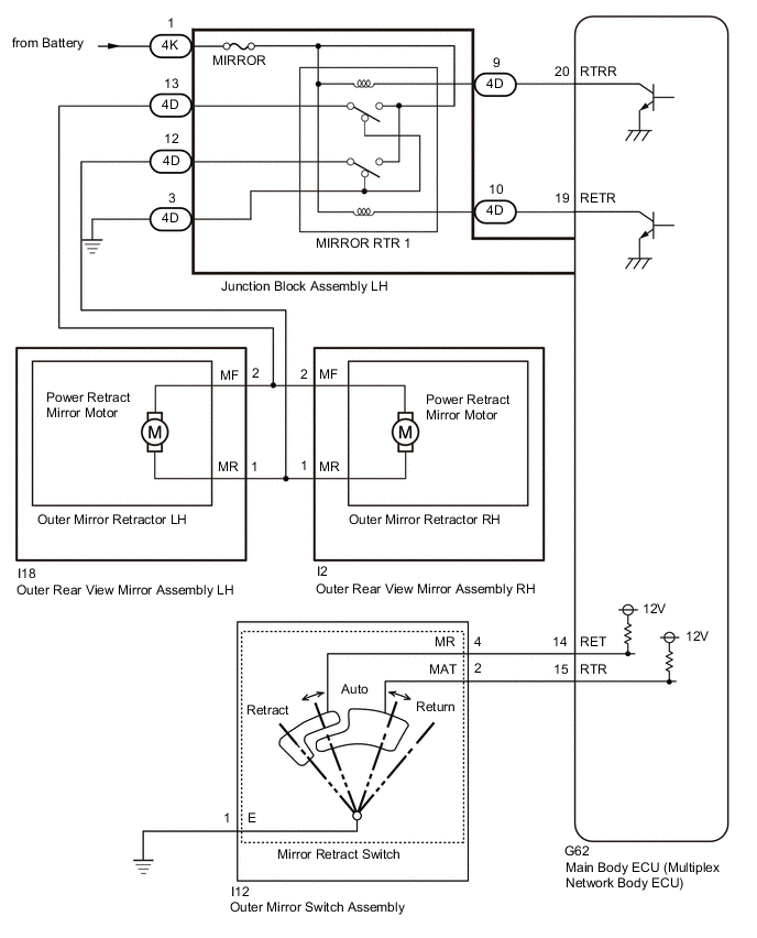
The outer mirror switch assembly (mirror retract switch) sends the auto retractable outer mirror switch signal to the main body ECU (multiplex network body ECU). The main body ECU (multiplex network body ECU) sends the auto retract/return signal to the outer rear view mirror assemblies, which then control the mirrors.
When the main body ECU (multiplex network body ECU) receives a door lock output signal while the outer mirror switch assembly (mirror retract switch) is in the auto position, the main body ECU (multiplex network body ECU) operates the power retract mirror motors built into the outer rear view mirror assemblies to retract or return the outer rear view mirror assemblies.
WIRING DIAGRAM
CAUTION / NOTICE / HINT
Note
-
If necessary, the function can be set to the default setting through the customize function.
-
If the main body ECU (multiplex network body ECU) is replaced, refer to the Service Bulletin.
-
As the door control battery is installed between the vehicle battery and main body ECU (multiplex network body ECU), first perform the inspections in On-Vehicle Inspection to confirm that there are no malfunctions in the power source circuit for the main body ECU (multiplex network body ECU) before performing this troubleshooting procedure.
PROCEDURE
-
CHECK WIRELESS DOOR LOCK CONTROL SYSTEM
-
Check the wireless door lock control system.
OK Wireless door lock control system is normal. Result Proceed to OK NG
NG 
GO TO WIRELESS DOOR LOCK CONTROL SYSTEM Click here
OK 
-
-
CHECK SMART ENTRY AND START SYSTEM (for Entry Function)
-
Check the smart entry and start system (for Entry Function).
OK Smart entry and start system (for Entry Function) is normal. Result Proceed to OK NG
NG
GO TO SMART ENTRY AND START SYSTEM (for Entry Function) Click here
OK
-
-
READ VALUE USING GTS (AUTO MIRROR SW)
-
Connect the GTS to the DLC3.
-
Turn the engine switch on (IG).
-
Turn the GTS on.
-
Enter the following menus: Body Electrical / Main Body / Data List.
-
Read the Data List according to the display on the GTS.
Body Electrical > Main Body > Data ListTester Display Measurement Item Range Normal Condition Diagnostic Note Auto Mirror SW Mirror retract switch signal OFF or ON OFF: Mirror retract switch not in auto position
ON: Mirror retract switch in auto position
-
Body Electrical > Main Body > Data ListTester Display Auto Mirror SW OK On the GTS screen, ON or OFF is displayed for each item according to the table above. Result Proceed to OK NG
OK
REPLACE MAIN BODY ECU (MULTIPLEX NETWORK BODY ECU) Click here
NG
-
-
INSPECT OUTER MIRROR SWITCH ASSEMBLY (MIRROR RETRACT SWITCH)
-
Remove the outer mirror switch assembly.
-
Inspect the outer mirror switch assembly.
Result Proceed to OK NG
NG
REPLACE OUTER MIRROR SWITCH ASSEMBLY Click here
OK
-
-
CHECK HARNESS AND CONNECTOR (MAIN BODY ECU [MULTIPLEX NETWORK BODY ECU] - OUTER MIRROR SWITCH ASSEMBLY)
-
Disconnect the G62 main body ECU (multiplex network body ECU) connector.
-
Disconnect the I12 outer mirror switch assembly connector.
-
Measure the resistance according to the value(s) in the table below.
Standard Resistance Tester Connection Condition Specified Condition G62-15 (RTR) - I12-2 (MAT) Always Below 1 Ω G62-15 (RTR) or I12-2 (MAT) - Body ground Always 10 kΩ or higher Result Proceed to OK NG
OK
REPLACE MAIN BODY ECU (MULTIPLEX NETWORK BODY ECU) Click here
NG
REPAIR OR REPLACE HARNESS OR CONNECTOR
-