POWER MIRROR CONTROL SYSTEM(w/ Memory) AUTO Power Retract Mirrors do not operate
DESCRIPTION
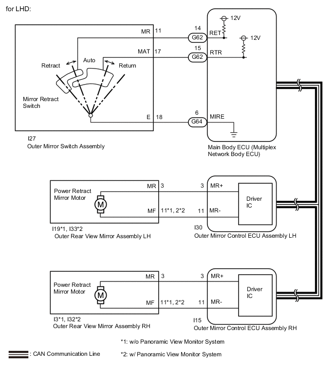
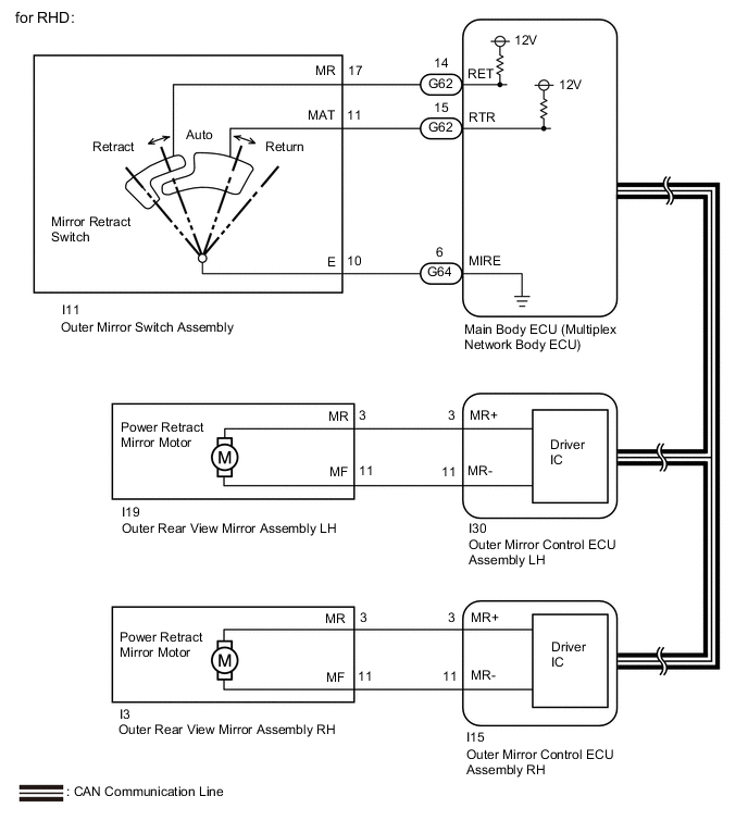
When the outer mirror switch assembly is set to auto (neutral position), an auto signal is detected by the main body ECU (multiplex network body ECU). When locking and unlocking all doors with the engine switch off, the main body ECU (multiplex network body ECU) sends return/retract signals to the outer mirror control ECU assembly via CAN communication. The outer mirror control ECU assembly returns and retracts the outer rear view mirror assembly based on the received signals.
WIRING DIAGRAM
CAUTION / NOTICE / HINT
Note
-
First perform the communication function inspections in How to Proceed with Troubleshooting to confirm that there are no CAN communication malfunctions before troubleshooting this problem.
-
If the main body ECU (multiplex network body ECU) is replaced, refer to the Service Bulletin.
-
As the door control battery is installed between the vehicle battery and main body ECU (multiplex network body ECU), first perform the inspections in On-Vehicle Inspection to confirm that there are no malfunctions in the power source circuit for the main body ECU (multiplex network body ECU) before performing this troubleshooting procedure.
PROCEDURE
-
CHECK POWER RETRACT MIRROR FUNCTION
-
Check power retract mirror function.
OK Power retract mirror function is normal. Result Proceed to OK NG
NG 
GO TO OTHER FLOWCHART (Power Retractable Mirrors do not Operate with Power Retract Mirror Switch) Click here
OK 
-
-
CHECK WIRELESS DOOR LOCK CONTROL SYSTEM
-
Check the wireless door lock control system.
OK Wireless door lock control system is normal. Result Proceed to OK NG
NG
GO TO WIRELESS DOOR LOCK CONTROL SYSTEM Click here
OK
-
-
CHECK SMART ENTRY AND START SYSTEM (for Entry Function)
-
Check the smart entry and start system (for Entry Function).
OK Smart entry and start system (for Entry Function) is normal. Result Proceed to OK NG
NG
GO TO SMART ENTRY AND START SYSTEM (for Entry Function) Click here
OK
-
-
READ VALUE USING GTS (AUTO MIRROR SW)
-
Connect the GTS to the DLC3.
-
Turn the engine switch on (IG).
-
Turn the GTS on.
-
Enter the following menus: Body Electrical / Main Body / Data List.
-
Read the Data List according to the display on the GTS.
Body Electrical > Main Body > Data ListTester Display Measurement Item Range Normal Condition Diagnostic Note Auto Mirror SW Mirror retract switch signal OFF or ON OFF: Mirror retract switch not in auto position
ON: Mirror retract switch in auto position
-
Body Electrical > Main Body > Data ListTester Display Auto Mirror SW OK On the GTS screen, ON or OFF is displayed for each item according to the table above. Result Proceed to OK NG
OK
REPLACE MAIN BODY ECU (MULTIPLEX NETWORK BODY ECU) Click here
NG
-
-
INSPECT OUTER MIRROR SWITCH ASSEMBLY (MIRROR RETRACTOR SWITCH)
-
Remove the outer mirror switch assembly.
-
Inspect the outer mirror switch assembly.
Result Proceed to OK NG
NG
REPLACE OUTER MIRROR SWITCH ASSEMBLY Click here
OK
-
-
CHECK HARNESS AND CONNECTOR (OUTER MIRROR SWITCH ASSEMBLY - MAIN BODY ECU [MULTIPLEX NETWORK BODY ECU])
-
Disconnect the I27*1 or I11*2 outer mirror switch assembly connector.
-
*1: for LHD
-
*2: for RHD
-
-
Disconnect the G62 and G64 main body ECU (multiplex network body ECU) connectors.
-
Measure the resistance according to the value(s) in the table below.
Standard Resistance for LHD Tester Connection Condition Specified Condition I27-11 (MR) - G62-14 (RET) Always Below 1 Ω I27-17 (MAT) - G62-15 (RTR) Always Below 1 Ω I27-18 (E) - G64-6 (MIRE) Always Below 1 Ω I27-11 (MR) or G62-14 (RET) - Body ground Always 10 kΩ or higher I27-17 (MAT) or G62-15 (RTR) - Body ground Always 10 kΩ or higher I27-18 (E) or G64-6 (MIRE) - Body ground Always 10 kΩ or higher for RHD Tester Connection Condition Specified Condition I11-17 (MR) - G62-14 (RET) Always Below 1 Ω I11-11 (MAT) - G62-15 (RTR) Always Below 1 Ω I11-10 (E) - G64-6 (MIRE) Always Below 1 Ω I11-17 (MR) or G62-14 (RET) - Body ground Always 10 kΩ or higher I11-11 (MAT) or G62-15 (RTR) - Body ground Always 10 kΩ or higher I11-10 (E) or G64-6 (MIRE) - Body ground Always 10 kΩ or higher Result Proceed to OK NG
OK
REPLACE MAIN BODY ECU (MULTIPLEX NETWORK BODY ECU) Click here
NG
REPAIR OR REPLACE HARNESS OR CONNECTOR
-