SLIDE DOOR REASSEMBLY
CAUTION / NOTICE / HINT
Tech Tips
-
Use the same procedure for the RH and LH sides.
-
The procedure listed below is for the LH side.
-
A bolt without a torque specification is shown in the standard bolt chart.
PROCEDURE
-
INSTALL LOWER SLIDE DOOR ROLLER ARM LH
-
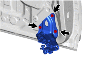
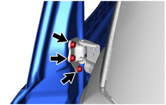
Install the lower slide door roller arm LH with the 3 bolts.
- Torque:
- 19.5 N*m { 199 kgf*cm, 14 ft.*lbf }
-
-
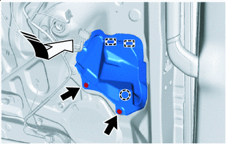
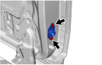
INSTALL SLIDE DOOR ROLLER ASSEMBLY LH
-
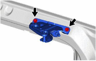
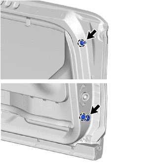
Install the silde door roller assembly LH with the 2 bolts.
- Torque:
- 11.5 N*m { 117 kgf*cm, 8 ft.*lbf }
-
-
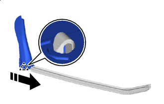
INSTALL CENTER SLIDE DOOR HINGE ASSEMBLY LH
-
When a new slide door center hinge assembly LH:
Remove the center roller protector LH.
-
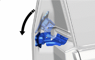

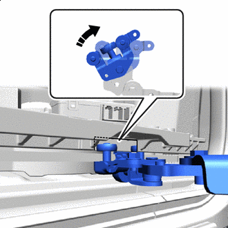
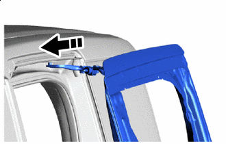
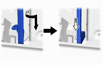
Install in this Direction Install the center slide door hinge assembly LH to the center slide door rail LH as shown in the illustration.
-
Move the center slide door hinge assembly LH to the rear of the slide rail.
-
-
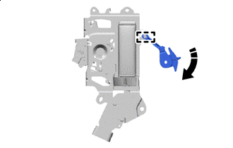
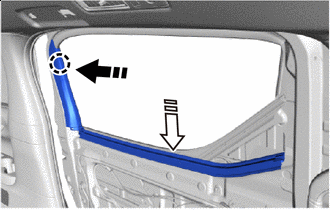
INSTALL SLIDE DOOR LH
-
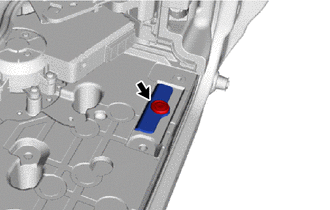
Clockwise Rotate the roller part of the lower slide door roller arm LH clockwise to connect the lower slide door roller arm LH to the cutout of the slide door motor unit LH.
Note
-
Support the lower portion of the slide door LH when disconnecting the lower slide door roller arm LH, as the slide door LH becomes unstable.
-
Work with 2 or more persons when connecting the slide door LH in order to prevent deformation and damage.
-
-
Install in this Direction Install the slide door roller assembly LH as shown in the illustration.
-
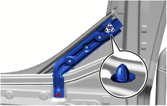
Install the center slide door hinge assembly LH with the 3 bolts.
- Torque:
- 19.5 N*m { 199 kgf*cm, 14 ft.*lbf }
-
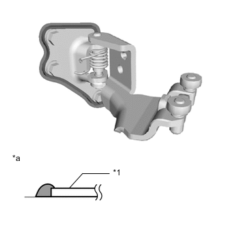
*1 Center Slide Door Hinge Assembly LH *a Section 
Anti-rust Coating Using a brush, apply anti-rust coating to the center slide door hinge assembly LH as shown in the illustration.
-
Move the slide door LH so that the bolt holes are visible.
-
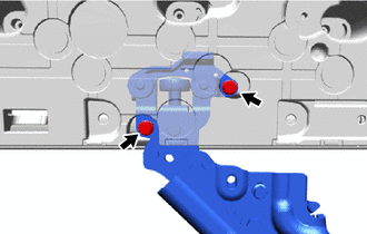
Connect the lower slide door roller arm LH to the slide door motor unit LH with the 2 bolts.
- Torque:
- 7.8 N*m { 80 kgf*cm, 69 in.*lbf }
-
-
INSTALL LOWER SLIDE DOOR RAIL PLATE LH
-
Install the lower slide door rail plate LH with the clip.
-
-
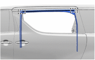
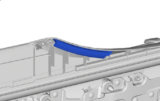
INSTALL UPPER SLIDE DOOR RAIL CUSHION LH
-
Install in this Direction Install the upper slide door rail cushion LH with the clip.
-
-
INSTALL NO. 1 SIDE MUDGUARD BRACKET LH
-
INSTALL SLIDE DOOR MUDGUARD LH
-
INSTALL REAR DOOR NO. 3 WEATHERSTRIP LH
-
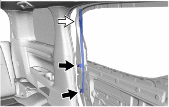
Attach the clip to install the rear door No. 3 weatherstrip LH.
-
-
INSTALL SLIDE DOOR FULL OPEN STOP LOCK ASSEMBLY LH
-
Apply MP grease to the sliding area of the slide door full open stop lock assembly LH.
-
Install the slide door full open stop lock assembly LH with the 2 bolts.
- Torque:
- 8.0 N*m { 82 kgf*cm, 71 in.*lbf }
-
Attach the clamp.
-
-
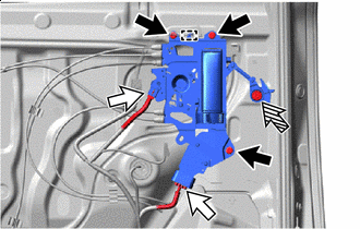
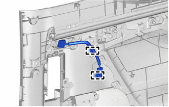
INSTALL REAR DOOR WIRE LH
-
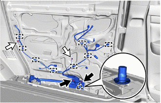

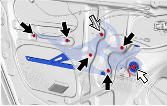
Bolt 
Ground Bolt Attach the clamp and clip.
-
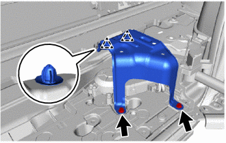
Install the 2 bolts.
- Torque:
- 8.0 N*m { 82 kgf*cm, 71 in.*lbf }
-
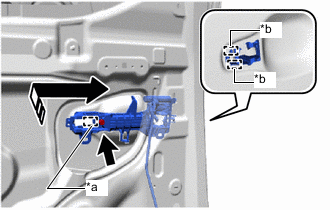
Connect the 2 ground wires with the 2 ground bolts.
- Torque:
- 8.4 N*m { 86 kgf*cm, 74 in.*lbf }
-
Bolt Ground Bolt 
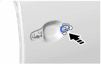
Connector Attach the clip.
-
Connect the ground wire with the ground bolt.
- Torque:
- 8.0 N*m { 82 kgf*cm, 71 in.*lbf }
-
Install the rear door wire LH with bolt.
- Torque:
- 8.0 N*m { 82 kgf*cm, 71 in.*lbf }
-
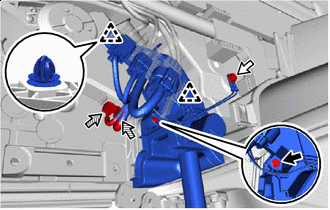
Connect the 2 connectors.
-
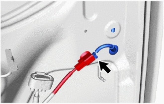
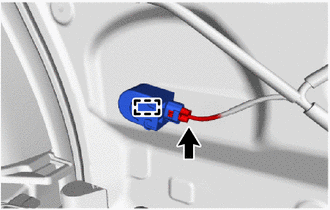
Airbag Connector Attach the clamp to connect the connector holder.
-
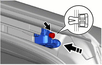
Before connecting the airbag connector, check that the position of the housing lock is correct as shown in the illustration.
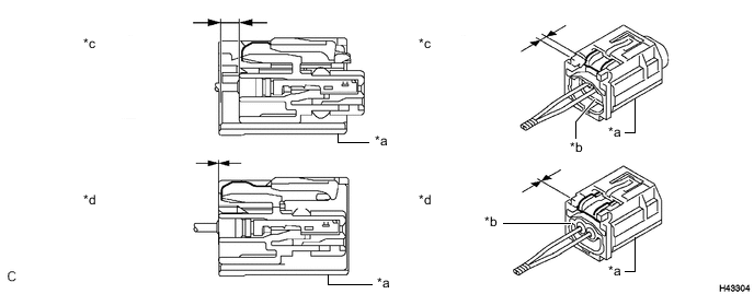
*a CPA *b Housing *c Correct *d Incorrect -
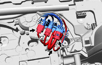
Connect the airbag connector.
Note
When connecting any airbag connector, take care not to damage the airbag wire harness.
-
While holding the CPA, be sure to engage the connectors until they are locked and check that the CPA is in its original position (when locking, make sure that a click sound can be heard).
Note
Do not push down the upper part of the CPA shown in the illustration when connecting the airbag connector.
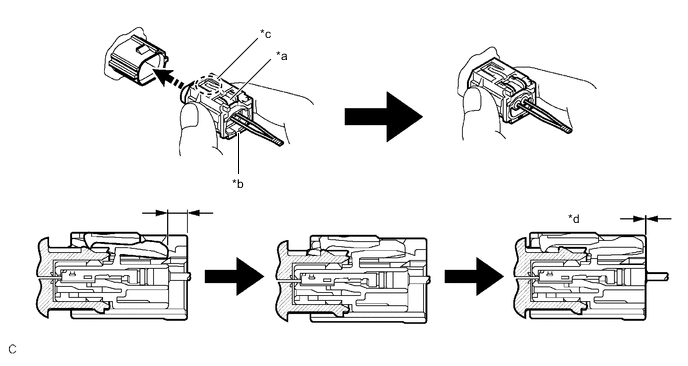
*a Housing Lock *b CPA *c CPA Upper Part *d Connection is Completed Connect Direction - -
-
-
Connect each connector.
-
-
INSTALL REAR SIDE STEP SUPPORT LH
-
Attach the clip to install the rear side step support LH with the 2 bolts.
- Torque:
- 7.5 N*m { 76 kgf*cm, 66 in.*lbf }
-
-
INSTALL REAR DOOR SCUFF PLATE LH
-
INSTALL POWER SLIDE DOOR SENSOR ASSEMBLY LH
-
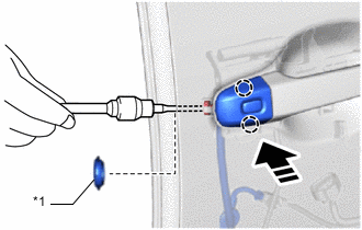
INSTALL REAR DOOR OUTSIDE HANDLE FRAME SUB-ASSEMBLY LH
-
Apply MP grease to the sliding area of the rear door outside handle frame sub-assembly LH.
-
*a Grommet *b Guide Install in this Direction Attach the grommet and guide to install the rear door outside handle frame sub-assembly LH as shown in the illustrasion.
-
Using a T30 "TORX" socket wrench, install the screw.
- Torque:
- 7.0 N*m { 71 kgf*cm, 62 in.*lbf }
-
-
INSTALL REAR DOOR FRONT OUTSIDE HANDLE PAD
-
Install in this Direction Attach the claw to install the rear door front outside handle pad.
-
-
INSTALL REAR DOOR REAR OUTSIDE HANDLE PAD
-
Install in this Direction Attach the claw to install the rear door rear outside handle pad.
-
-
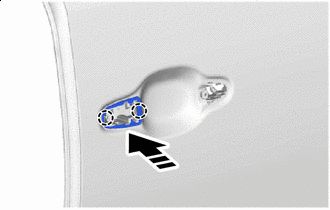
INSTALL REAR DOOR OUTSIDE HANDLE ASSEMBLY LH
-
Install in this Direction Install the rear door outside handle assembly LH as shown in the illustration.
-
-
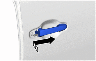
INSTALL REAR DOOR OUTSIDE HANDLE COVER LH
-
*1 Hole Plug Install in this Direction Attach the claw to install the rear door outside handle cover LH as shown in the illustration.
-
Using a T30 "TORX" socket wrench, install the screw.
- Torque:
- 7.0 N*m { 71 kgf*cm, 62 in.*lbf }
-
Install the hole plug.
-
Connect the connector.
-
-
INSTALL REAR SLIDE DOOR LOCK ASSEMBLY LH
-
INSTALL FRONT SLIDE DOOR LOCK ASSEMBLY LH
-
INSTALL CUSHION
-
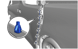
Attach the claw to install 2 new cushions.
-
-
INSTALL REAR DOOR BELT MOULDING LH
-
INSTALL REAR DOOR OUTSIDE MOULDING LH
-
INSTALL REAR DOOR REAR WINDOW FRAME MOULDING LH
-
INSTALL REAR DOOR UPPER WINDOW FRAME MOULDING LH
-
INSTALL REAR DOOR FRONT WINDOW FRAME MOULDING LH
-
INSTALL REAR DOOR REAR WINDOW GUIDE SUB-ASSEMBLY LH
-
Install in this Direction (1) 
Install in this Direction (2) Insert the rear door rear window guide sub-assembly LH as shown in the illustration.
-
Bolt Nut Install the rear door rear window guide sub-assembly LH with nut and 2 bolts.
- Torque:
- Nut
- 7.5 N*m { 76 kgf*cm, 66 in.*lbf }
- Bolt
- 7.5 N*m { 76 kgf*cm, 66 in.*lbf }
-
-
INSTALL POWER WINDOW REGULATOR MOTOR ASSEMBLY LH
-
INSTALL REAR DOOR WINDOW REGULATOR SUB-ASSEMBLY LH
-
Apply MP grease to the sliding area of the rear door window regulator sub-assembly LH.
-
Bolt Connector Temporarily Bolt Temporarily install the temporarily bolt to the rear door window regulator sub-assembly LH.
-
Temporarily install the rear door window regulator sub-assembly LH.
-
Install the rear door window regulator sub-assembly LH with the temporarily bolt and 5 bolts.
- Torque:
- Temporarily Bolt
- 7.5 N*m { 76 kgf*cm, 66 in.*lbf }
- Bolt
- 7.5 N*m { 76 kgf*cm, 66 in.*lbf }
-
Connect the connector.
-
-
INSTALL REAR DOOR GLASS RUN LH
-
Attach the guide to install the rear door glass run LH.
-
-
INSTALL REAR DOOR GLASS SUB-ASSEMBLY LH
-
Install in this Direction (1) Install in this Direction (2) Temporarily install the rear door glass sub-assembly LH.
Note
Be careful not to damage the rear door glass sub-assembly LH.
-
Install the rear door glass sub-assembly LH with the 2 bolts.
- Torque:
- 7.5 N*m { 76 kgf*cm, 66 in.*lbf }
-
-
INSTALL SUNSHADE HOOK
-
Install the 2 sunshade hooks.
-
-
INSTALL REAR SPEAKER ASSEMBLY
-
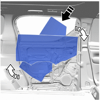
INSTALL NO. 2 SLIDE DOOR SERVICE HOLE COVER
-
Apply new butyl tape to the slide door panel.
-
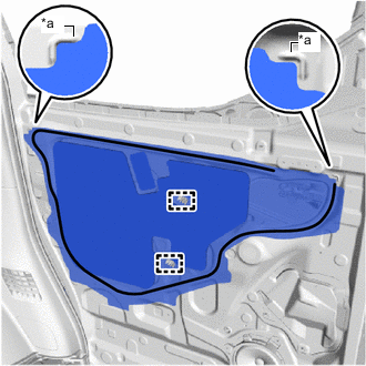
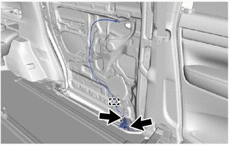
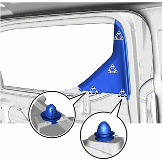
*a Reference Point 
Butyl Tape Pass the rear door inside locking cable assembly LH, rear door lock remote control cable assembly LH and wire harness through a new No. 2 slide door service hole cover, and then attach the No. 2 slide door service hole cover using the reference points on the front door panel.
Tech Tips
-
Securely install the No. 2 slide door service hole cover to prevent wrinkles and air bubbles.
-
There should be no wrinkles or folds after installing the No. 2 slide door service hole cover.
-
After installing the No. 2 slide door service hole cover, check the seal quality.
-
-
Install the 2 clamps.
-
Connect the wire harness.
-
-
INSTALL WIRELESS DOOR LOCK BUZZER
-
Attach the clamp to install the wireless door lock buzzer.
-
Connect the connector.
-
-
INSTALL SLIDE DOOR PANEL COVER SUB-ASSEMBLY LH
-
Install in this Direction Attach the claw and clamp to install the slide door panel cover sub-assembly LH as shown in the illustration.
-
Install the 2 screws.
-
-
INSTALL NO. 2 SIDE AIR BAG SENSOR ASSEMBLY
-
INSTALL REAR DOOR LOCKING CONTROL LINK SUB-ASSEMBLY LH
-
Install in this Direction Attach the guide to install the rear door locking conetrol link sub-assembly LH to the slide door handle assembly LH.
-
-
INSTALL SLIDE DOOR HANDLE ASSEMBLY LH
-
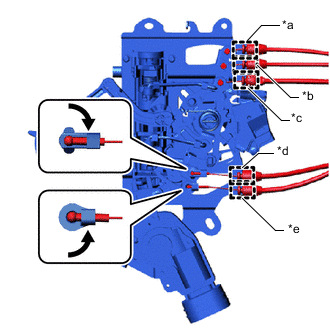
*a Green *b White *c Black *d Yellow *e Gray Connect Attach the guide to connect the each cable.
-
Attach the snap as shown in the illustration.
-
Bolt Connector Clip Attach the hook to install the slide door handle assembly LH with the 3 bolts.
- Torque:
- 7.5 N*m { 76 kgf*cm, 66 in.*lbf }
-
Install the clip.
-
Connect the 2 connectors.
-
-
INSTALL SLIDE DOOR DOWN FEMALE STOPPER
-
Install the slide door down female stopper with the 2 bolts.
- Torque:
- 7.5 N*m { 76 kgf*cm, 66 in.*lbf }
-
-
INSTALL REAR DOOR REAR GUIDE BRACKET GARNISH LH
-
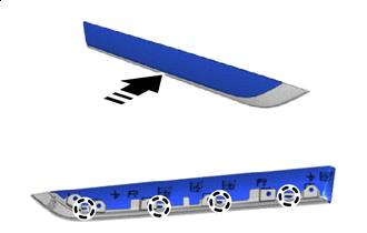
Install in this Direction Attach the clip to install the rear door rear guide bracket garnish LH to the rear door inner glass weatherstrip LH.
-
-
INSTALL REAR DOOR INNER GLASS WEATHERSTRIP WITH GARNISH
-
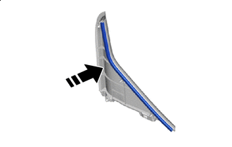
Install in this Direction (1) Install in this Direction (2) Attach the claw to install the rear door inner glass weatherstrip with garnish as shown in the illustration.
-
-
INSTALL REAR DOOR FRONT WINDOW GUIDE LH
-
Attach the clip to install the rear door front window guide LH with the screw.
-
-
INSTALL REAR DOOR NO. 3 GLASS RUN LH
-
Install in this Direction Install the rear door No. 3 glass run LH to the slide door window garnish LH.
-
-
INSTALL SLIDE DOOR WINDOW GARNISH LH
-
Attach the clip to insall the slide door window garnish LH.
-
-
INSTALL NO. 4 SIDE TRIM BASE PLATE (w/ Sunshade)
-
Install in this Direction Attach the claw to install the No. 4 side trim base plate to the rear No. 2 door trim ornament base.
-
-
INSTALL REAR NO. 2 DOOR TRIM ORNAMENT BASE (w/ Sunshade)
-
Install in this Direction Attach the guide and claw.
-
Install the rear No. 2 door trim ornament base together with the No. 4 side trim base plate with 9 screws as shown in the illustration.
-
-
INSTALL UPPER SLIDE DOOR TRIM BOARD LH (w/ Sunshade)
-
INSTALL REAR DOOR WIRING SUB-ASSEMBLY LH
-
Attach the clmap to install the rear door wiring sub-assembly LH.
-
-
INSTALL REAR NO. 2 SPEAKER ASSEMBLY
-
INSTALL REAR DOOR NO. 2 GLASS RUN LH
-
Install the rear door No. 2 glass run LH to the rear door trim board sub-assembly LH.
-
-
INSTALL REAR POWER WINDOW REGULATOR SWITCH ASSEMBLY
-
INSTALL REAR DOOR TRIM BOARD SUB-ASSEMBLY LH
-
Connect each connector.
-
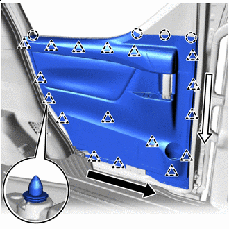
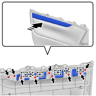
Order of Removal (1) Order of Removal (2) Attach the claw and clip to install the rear door trim board sub-assembly LH as shown in the illustration.
-
-
INSTALL NO. 3 SLIDE DOOR WEATHERSTRIP LH
-
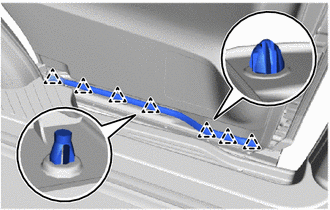
Attach the clip to install the No. 3 slide door weatherstrip LH.
-
-
INSPECT SLIDE DOOR SUB-ASSEMBLY LH
-
ADJUST SLIDE DOOR SUB-ASSEMBLY LH
-
CONNECT CABLE TO NEGATIVE BATTERY TERMINAL
Note
When disconnecting the cable, some systems need to be initialized after the cable is reconnected.
-
CHECK SRS WARNING LIGHT
-
PERFORM DIAGNOSTIC SYSTEM CHECK
-
INITIALIZE POWER WINDOW CONTROL SYSTEM
-
CHECK POWER WINDOW CONTROL SYSTEM
-
CHECK POWER DOOR LOCK CONTROL SYSTEM